
Apparatus and method for envelope tracking power amplification in wireless communication system

a wireless communication and envelope tracking technology, applied in the field of apparatus and a wireless communication amplifying power method, can solve the problems of time alignment method using either the distortion signal caused by the delay difference or the phase measurement of the test signal subject to low accuracy, and the spectrum characteristic of the output signal of the power amplifier is distorted

Inactive Publication Date: 2009-04-16
SAMSUNG ELECTRONICS CO LTD
View PDF5 Cites 153 Cited by
  • Summary
  • Abstract
  • Description
  • Claims
  • Application Information

AI Technical Summary

Problems solved by technology

If the time alignment is not performed accurately, the spectrum characteristic of the power amplifier output signal is distorted.
However, the time alignment method using either the distortion signal caused by the delay difference or the phase measurement of the test signal is subject to low accuracy because it is difficult to define a relational expression to derive the quantitative delay difference from the measurement.
Furthermore, such a method may require additional functions.
Accordingly, the correlation coefficient measurement results of the envelope signal and the baseband signal with respect to the RF signal amplified and output from the power amplifier are not independent of each other and interfere with each other.
As a result, it is difficult to measure the delay difference using the correlation coefficient measurement on the envelope signal and the baseband signal.

Method used


Image

  • Apparatus and method for envelope tracking power amplification in wireless communication system
  • Apparatus and method for envelope tracking power amplification in wireless communication system
  • Apparatus and method for envelope tracking power amplification in wireless communication system

Examples


Embodiment Construction

[0021]The following description with reference to the accompanying drawings is provided to assist in a comprehensive understanding of exemplary embodiments of the present invention as defined by the claims and their equivalents. It includes various specific details to assist in that understanding but these are to be regarded as merely exemplary. Accordingly, those of ordinary skill in the art will recognize that various changes and modifications of the embodiments described herein can be made without departing from the scope and spirit of the invention. Also, descriptions of well-known functions and constructions are omitted for clarity and conciseness.

[0022]Exemplary embodiments of the present invention provide an apparatus and a method for an Envelope Tracking (ET) based power amplification to compensate for a time delay by independently measuring a time delay difference per path in a wireless communication system.

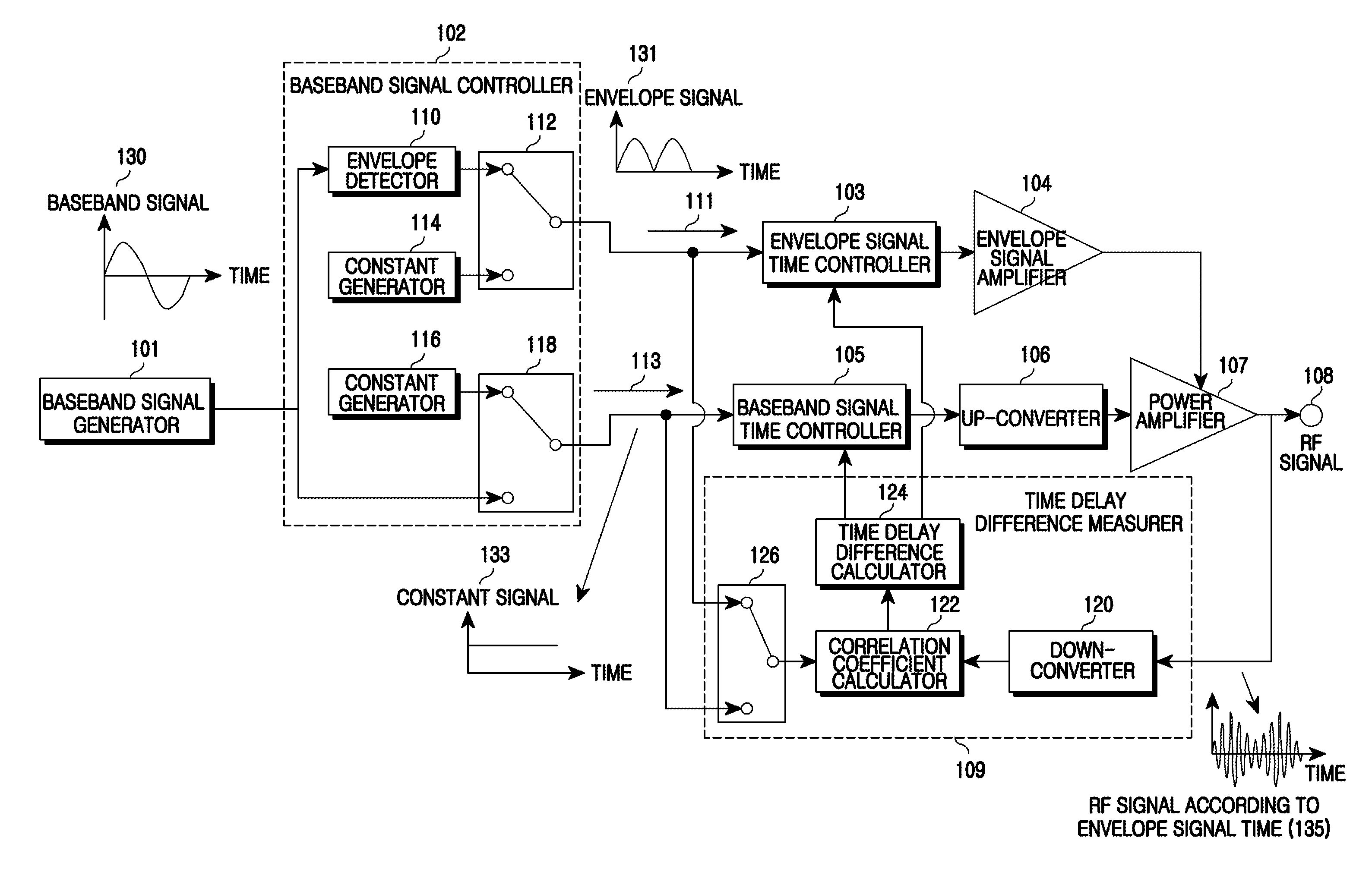
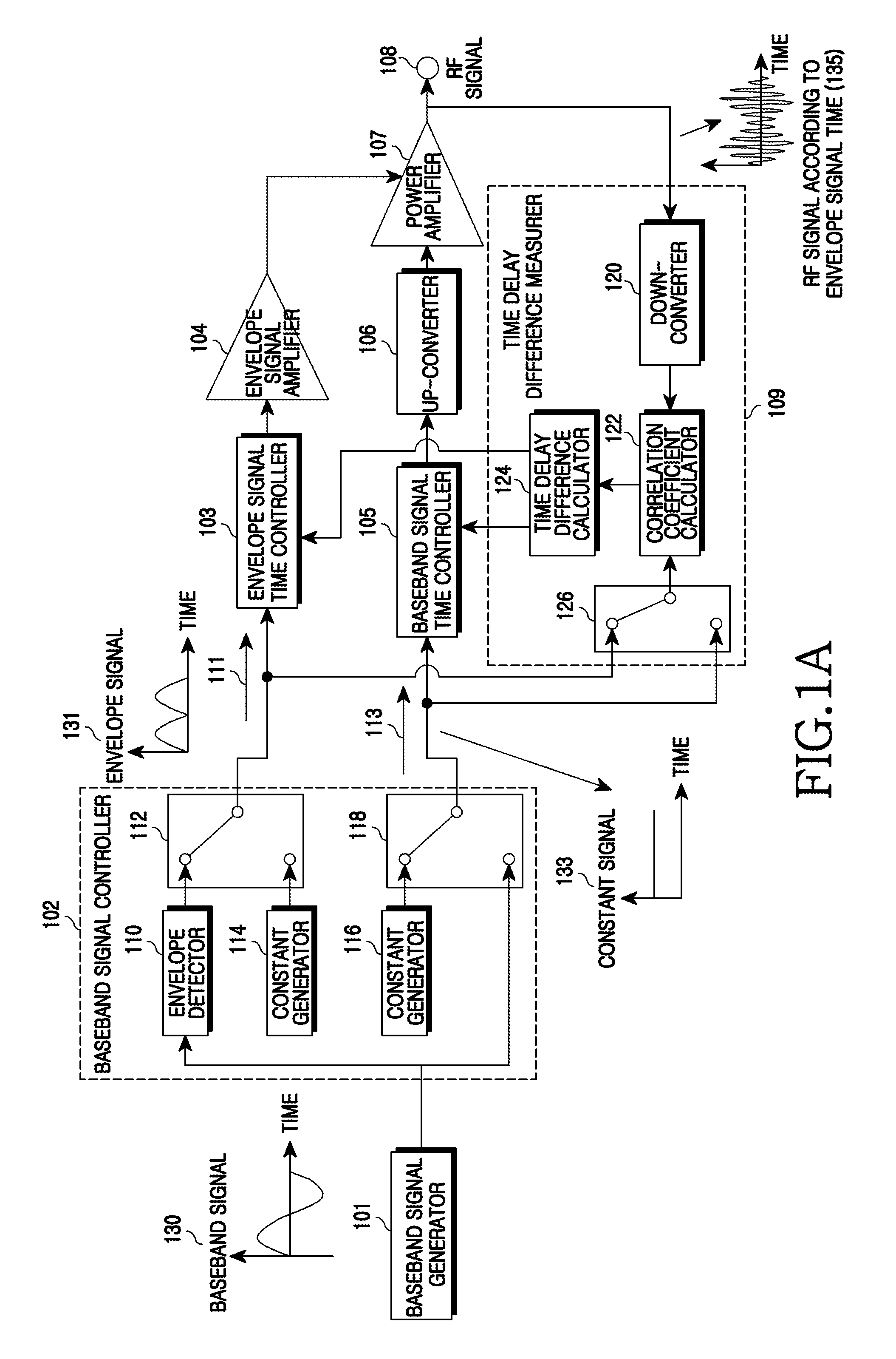
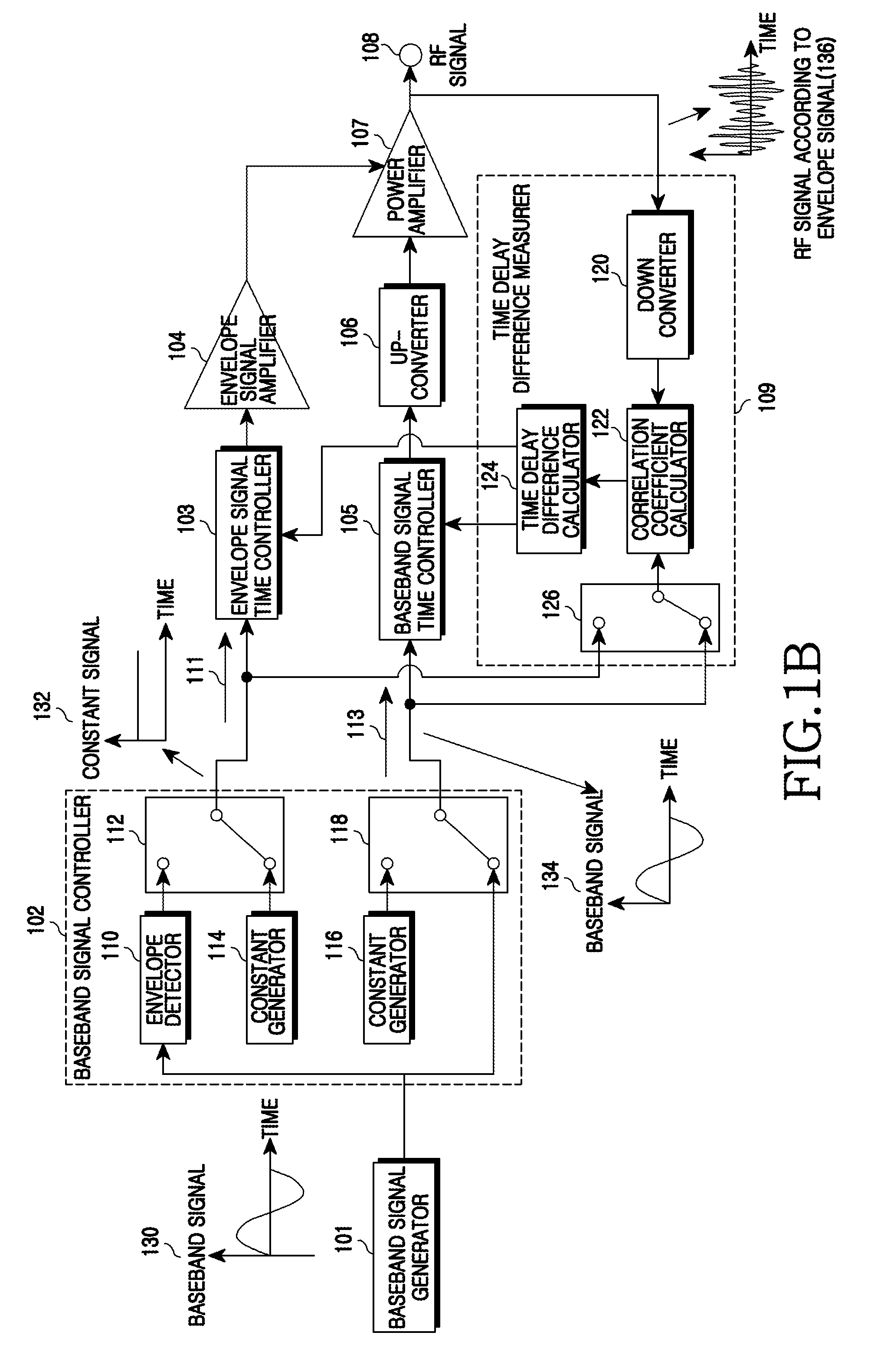
[0023]FIGS. 1A and 1B are block diagrams of a power amplification t...


PUM


Abstract

An apparatus and a method for Envelope Tracking (ET) power amplification in a wireless communication system are provided. The apparatus includes a baseband signal controller for outputting an envelope signal in an envelope signal path and outputting a constant signal in a baseband signal path when measuring a time delay of the envelope signal path, and for outputting a constant signal in the envelope signal path and outputting a baseband signal in the baseband signal path when measuring a time delay of the baseband signal path, a time delay difference measurer for measuring a time delay of each path by calculating a correlation coefficient between the envelope signal path and the baseband signal path and a signal time controller for setting a time delay in a corresponding path using the time delay difference of each path and aligning times.

Description

PRIORITY[0001]This application claims the benefit under 35 U.S.C. §119(a) of a Korean patent application filed in the Korean Intellectual Property Office on Oct. 10, 2007 and assigned Serial No. 2007-101826, the entire disclosure of which is hereby incorporated by reference.BACKGROUND OF THE INVENTION[0002]1. Field of the Invention[0003]The present invention relates generally to an apparatus and a method for amplifying power in a wireless communication. More particularly, the present invention relates to an apparatus and a method for power amplification by Envelope Tracking (ET) to compensate for a delay difference by independently measuring a delay per path.[0004]2. Description of the Related Art[0005]In response to the wide use of wireless communications, it is necessary for a mobile terminal and a base station system to amplify a digital-modulated signal up to an intended transmit power using a Radio Frequency (RF) power amplifier and to transmit the amplified signal. In doing so...

Claims


Application Information

Patent Timeline
Patent Type & Authority Applications(United States)
IPC IPC(8): H04L25/49
CPCH03F1/0222H03F3/24H04L27/361H03F2200/451H03F2200/504H03F2200/102H04B1/04
Inventor KIM, BYUNG-WOOK
Owner SAMSUNG ELECTRONICS CO LTD
Learn More