Receiver apparatus for use in optical space transmission system

a technology for receiving apparatus and optical space, applied in electrical apparatus, electromagnetic transmission, close-range type systems, etc., can solve the problem of complicated optical axis adjustment mechanism, and achieve the effect of reducing the influence of optical beat interference noise and reducing management costs

Inactive Publication Date: 2009-04-16
PANASONIC CORP
View PDF0 Cites 18 Cited by
  • Summary
  • Abstract
  • Description
  • Claims
  • Application Information

AI Technical Summary

Benefits of technology

[0025]As described above, according to the present invention, even when the wave lengths of the optical signals outputted from the plurality of light sources are the same as one another or approximate to one another, an influence of the optical beat interference noise can be reduced. Owing to this, when an optical space transmission is performed, it is not required to select light sources which emit light beams having wave lengths which are different from one another. Thus, a management cost can be made lower than that required when light sources which emit light beams having wave lengths which are different from one another are used.

Problems solved by technology

In this case, since it is needed to maintain an accuracy of a position of the adjusted optical axis, a complicated optical axis adjustment mechanism is required.

Method used


Image

  • Receiver apparatus for use in optical space transmission system
  • Receiver apparatus for use in optical space transmission system
  • Receiver apparatus for use in optical space transmission system

Examples


Embodiment Construction

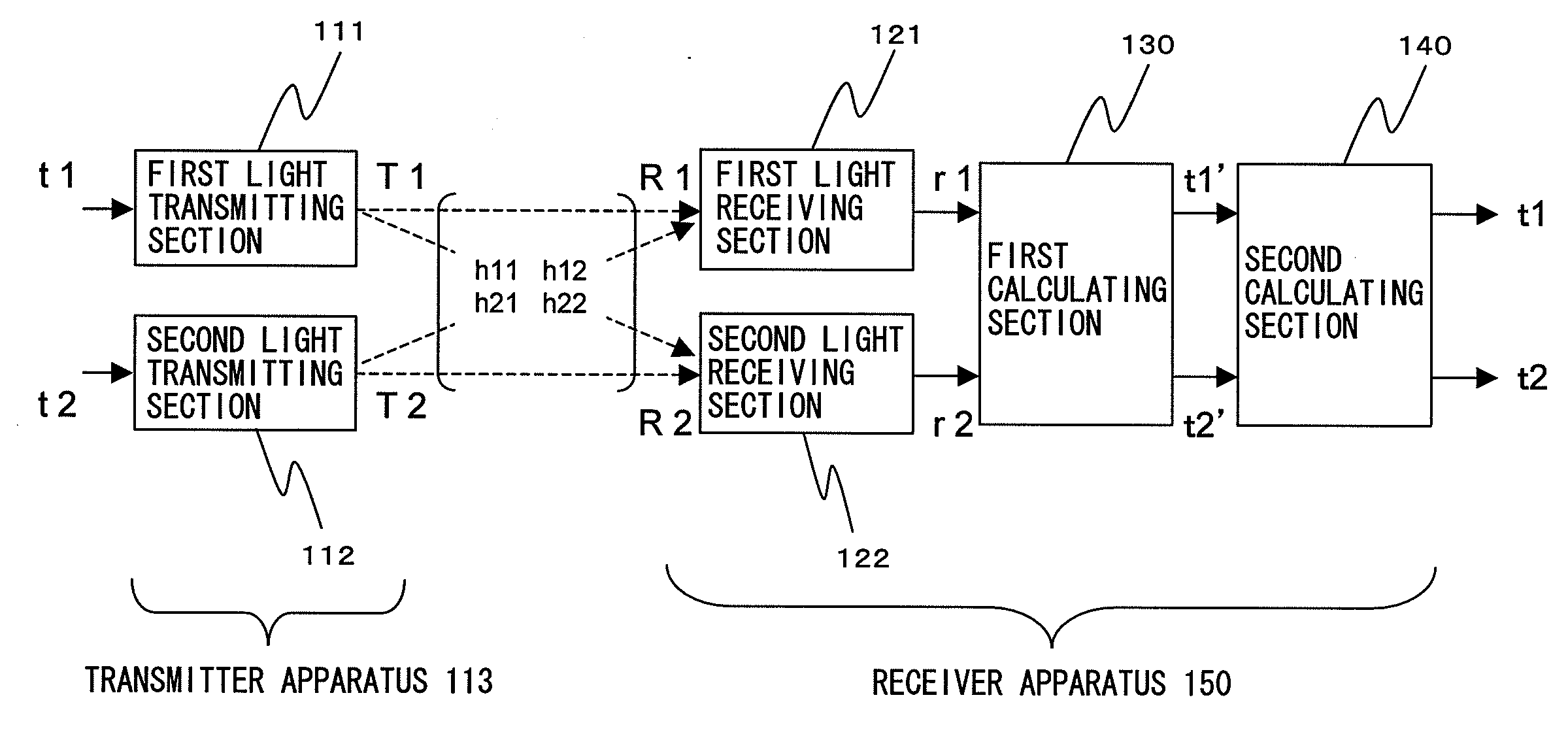
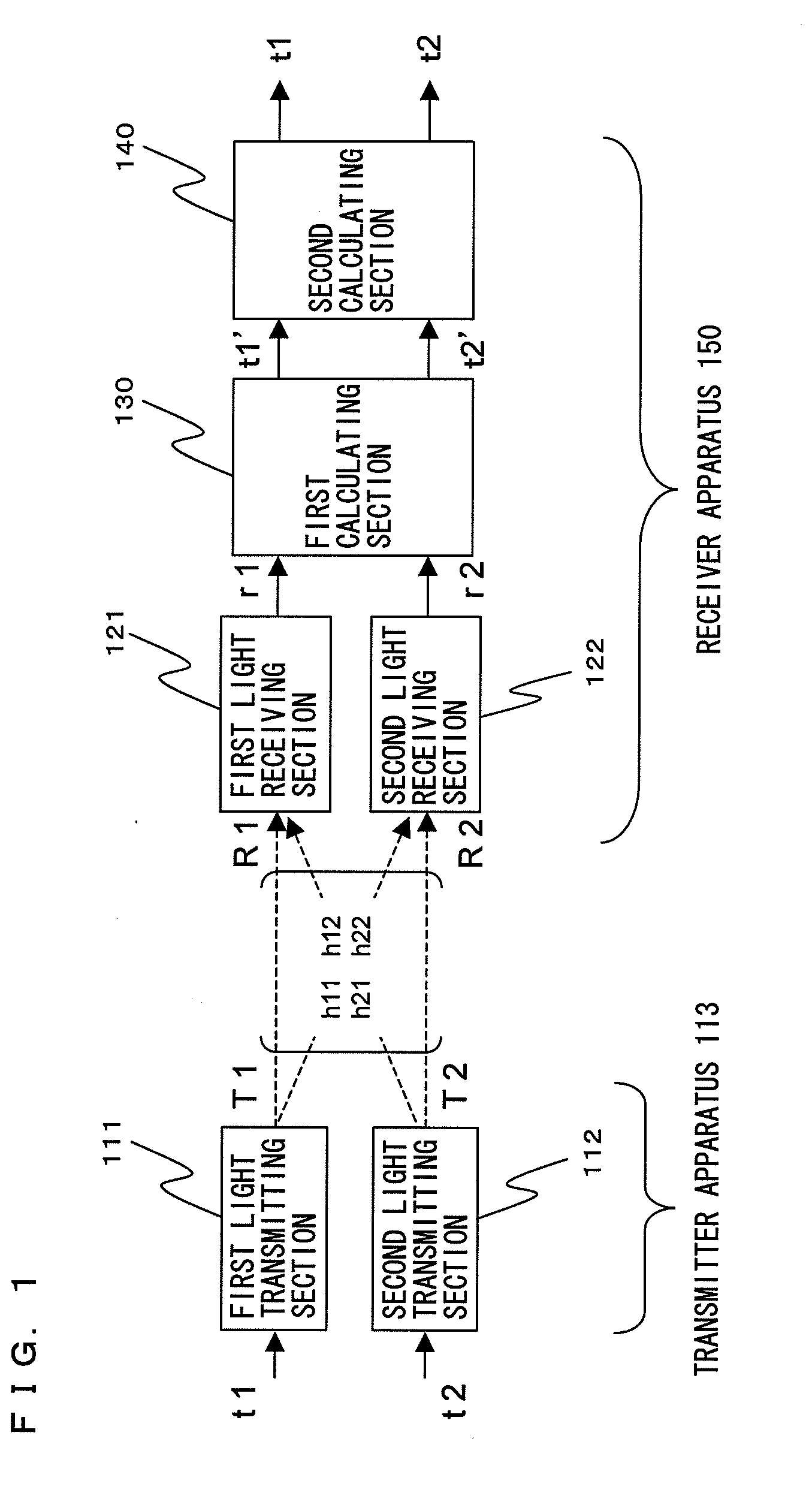
[0045]FIG. 1 is a diagram illustrating a configuration of an optical space transmission system using a receiver apparatus according to an embodiment of the present invention. As shown in FIG. 1, this optical space transmission system comprises a transmitter apparatus 113 and a receiver apparatus 150. The transmitter apparatus 113 includes a first light transmitting section 111 and a second light transmitting section 112. The receiver apparatus 150 includes a first light receiving section 121, a second light receiving section 122, a first calculating section 130, and a second calculating section 140. Note that although hereinafter, a case where two light transmitting sections and two light receiving sections are included respectively is mainly described, three or more light transmitting sections and three or more light receiving sections may be included respectively.

[0046]Hereinafter, operations of the transmitter apparatus 113 and the receiver apparatus 150 will be described. The fi...


PUM


Abstract

There included are a plurality of light receiving sections (121, 122) for receiving a plurality of optical signals (R1, R2) and respectively converting the received optical signals to a plurality of electrical signals (r1, r2); a first calculating section (130) for subjecting the plurality of electrical signals (r1, r2) to a process of canceling interference components occurring due to propagation of the plurality of optical signals through space; and a second calculating section (140) for calculating, with respect to each of the plurality of electrical signals whose interference components have been canceled by the first calculating section, whether or not a distortion occurring due to optical beat interference has a value less than or equal to a predetermined permissible value.

Description

TECHNICAL FIELD[0001]The present invention relates to a receiver apparatus for use in an optical transmission system in which light is used as a wirelessly transmitted signal and more particularly, to a receiver apparatus for use in an optical space transmission system in which optical signals emitted from a plurality of light transmitting sections are received.BACKGROUND ART[0002]An optical space transmission system for transmitting a wirelessly transmitted signal which is light used through a free space (hereinafter, referred to as an optical signal) is used in a remote-control device or the like for conducting channel selection or the like on a household audio / video appliance or a television set for indoor use. A data transmission speed at which this remote-control device transmits an optical signal is comparatively low, approximately 1 Mbps or less. Therefore, even when an angle of divergence of a light beam containing an optical signal emitted by this remote-control device whic...

Claims


Application Information

Patent Timeline
Patent Type & Authority Applications(United States)
IPC IPC(8): H04B10/10H04B10/114
CPCH04B10/1141H04B10/11H04B10/60
Inventor SASAI, HIROYUKINIIHO, TSUTOMUNAKASO, MARIKO
Owner PANASONIC CORP
Why Eureka
Try Eureka