Cyclonic separation apparatus

a technology of cyclonic separation and cyclone, which is applied in the direction of filter regeneration, liquid separation agent use, dispersed particle filtration, etc., can solve the problems of time-consuming process, limited use of vacuum cleaners, and restrictive number of peripheral arrangements of higher-efficiency stages, and achieve high separation efficiency

Inactive Publication Date: 2009-04-23
HOOVER LIMITED
View PDF31 Cites 95 Cited by
  • Summary
  • Abstract
  • Description
  • Claims
  • Application Information

AI Technical Summary

Benefits of technology

[0010]The multi-stage, series connected cyclone separators of the apparatus provide a high separation efficiency, yet the annular arrangement of the stages makes the device compact and enables the apparatus to be utilised in a vacuum cleaner.

Problems solved by technology

The height of this arrangement renders it of limited use to vacuum cleaners, where compact dimensions are required.
The collection chambers must be emptied individually, which can be a time consuming process since several parts are required to be removed from the separator unit.
However, the peripheral arrangement of the higher-efficiency stages is restrictive of the number of cyclones possible in the individual stages, having regard to the dimensional limitations applicable to vacuum cleaners.

Method used


Image

  • Cyclonic separation apparatus
  • Cyclonic separation apparatus
  • Cyclonic separation apparatus

Examples


first embodiment

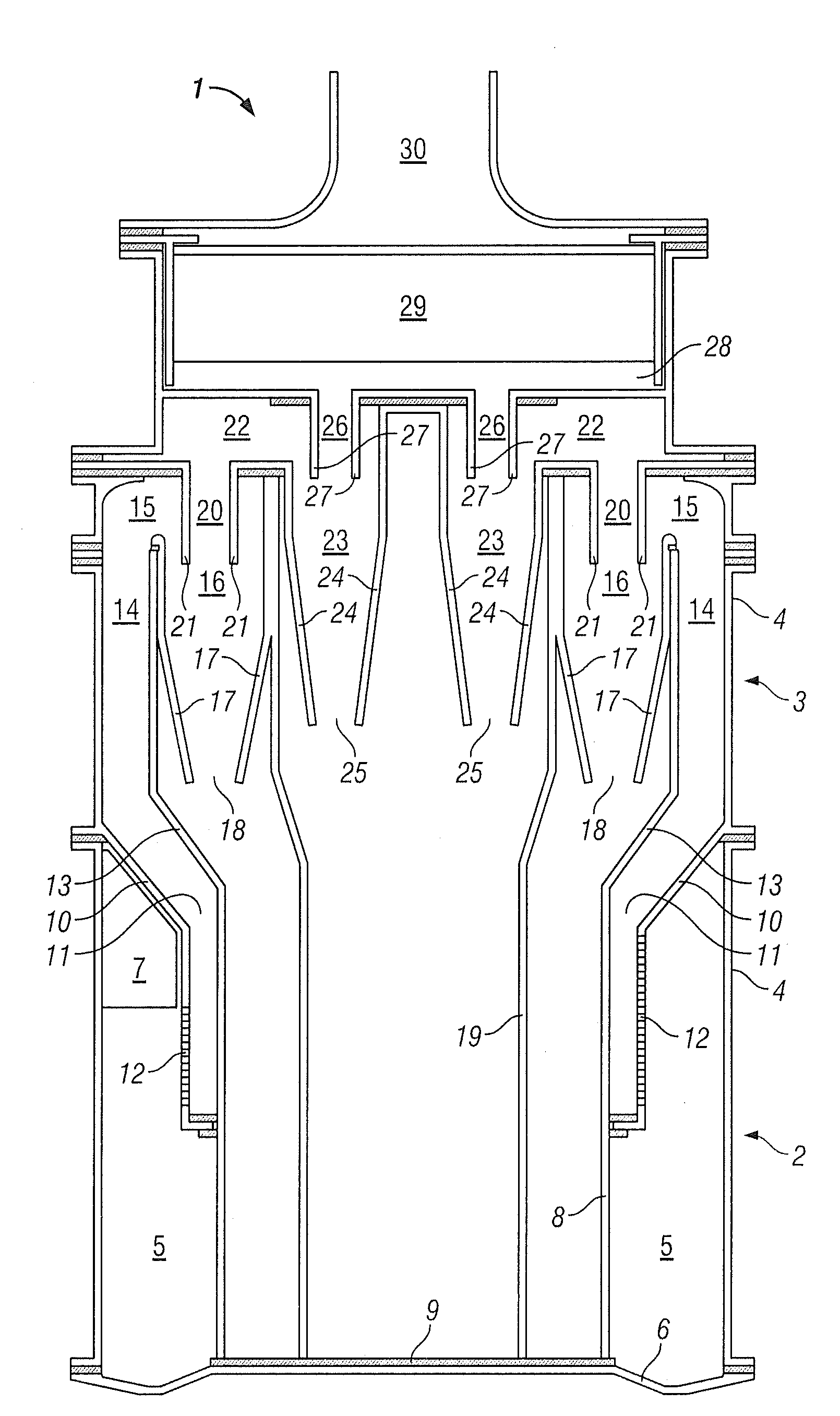
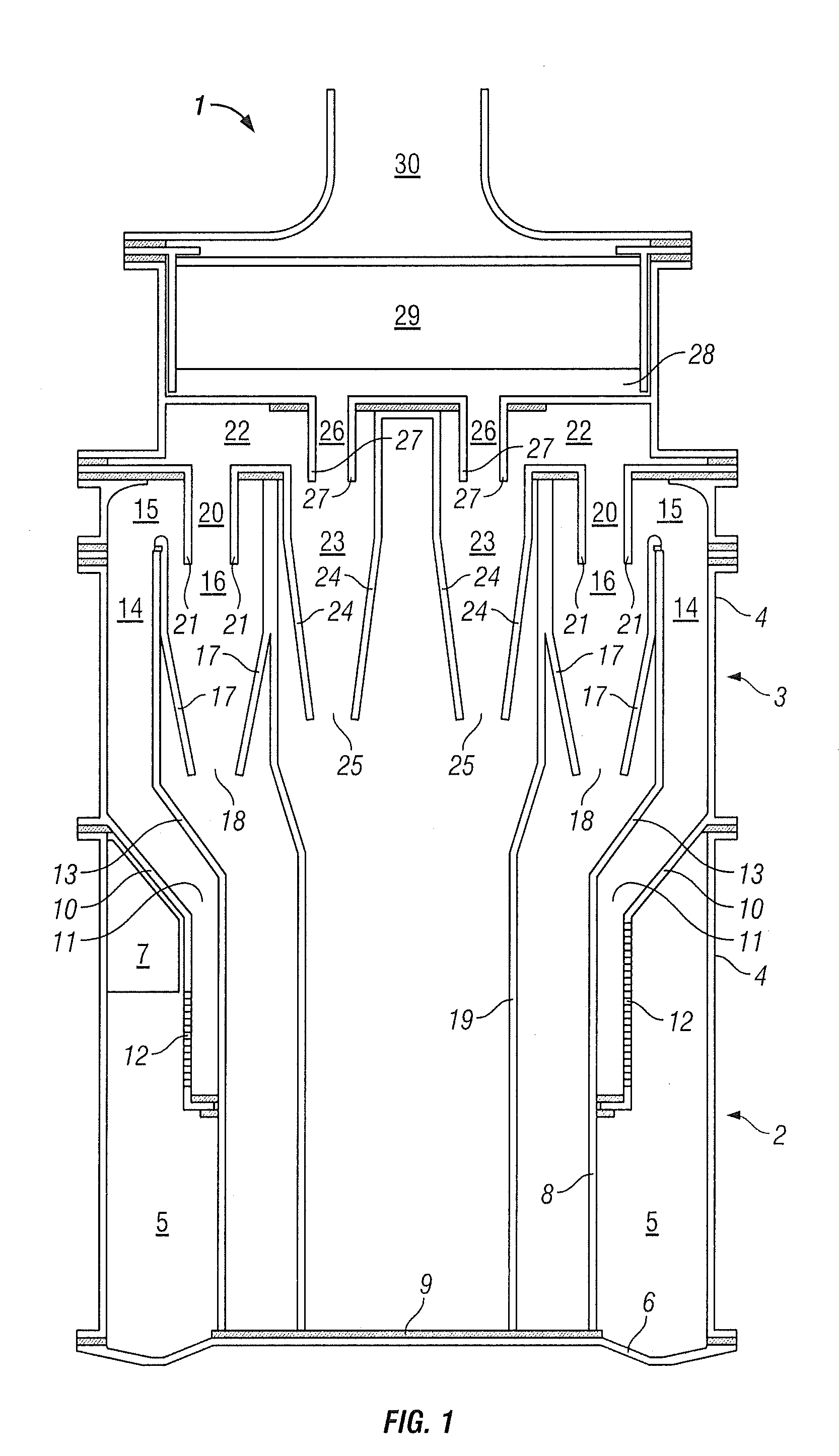
[0030]In accordance with the present invention, the cyclones 23 of the second downstream stage 51 are clustered together in an annular group about the central longitudinal axis of the apparatus 1 and are nested within the first plurality of cyclones 16. Each of the cyclones 23 of the second downstream stage 51 is fed air that has been partly cleaned, initially by the single low efficiency cyclone of the upstream stage 2 and then by the cyclones 16 of the first downstream stage 50. The inlets 22 of the cyclones 23 of the second downstream stage 51 extend radially inwardly with respect to the cyclones 16 of the first downstream stage 50. The cyclones 23 of the second downstream stage 51 each comprise a frustro-conical side wall 24 which extends down from the inlet 22 and tapers to a small diameter with the base of the side wall 24 defining an outlet 25.

[0031]The cyclones 23 of the second downstream stage 51 extend longitudinally of the apparatus 1 and are disposed within the confines ...

second embodiment

[0039]In the present invention, the cyclones of the first downstream stage may be connected to the cyclones of the second downstream stage via one or more intermediate stages, each comprising an annular array of parallel-connected cyclones staggered upwardly along the vertical central axis of the apparatus.

third embodiment

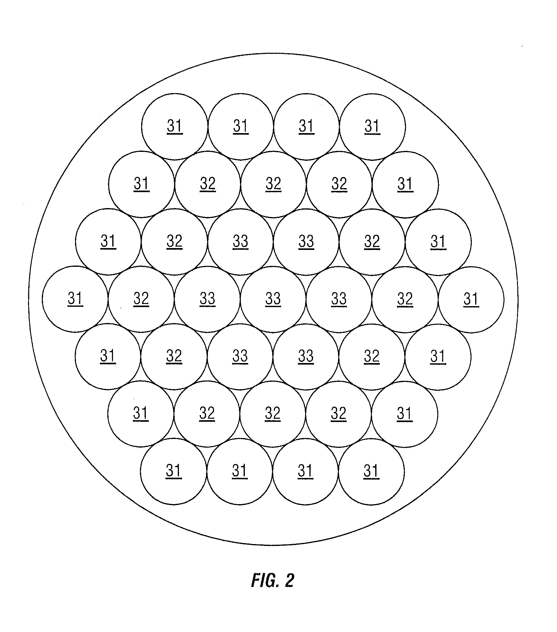
[0040]Referring to FIG. 2, there is shown a plan view of the downstream separation stage of a cyclonic separation apparatus in accordance with the present invention, with the downstream separation stage comprising three levels of cyclonic separation.

[0041]In this embodiment, the downstream separation stage comprises:[0042]a first downstream stage, having a plurality of parallel connected high efficiency cyclones 31 arranged in an annular configuration;[0043]a second downstream stage, having a plurality of parallel connected higher efficiency cyclones 32 arranged in an annular configuration and nested within the first downstream stage; and[0044]a third downstream stage, having a plurality of parallel connected higher efficiency cyclones 33 clustered together and nested within the second downstream stage.

[0045]The cyclones 31, 32, 33 of the first, second and third downstream stages are staggered longitudinally of the apparatus 1, with those cyclones arranged closer to the central long...


PUM

PropertyMeasurementUnit
heightaaaaaaaaaa
timeaaaaaaaaaa
diameteraaaaaaaaaa

Abstract

A cyclonic separation apparatus comprises a plurality of series-connected separation stages 50,51, each comprising a plurality of cyclone separators 16/23 connected in parallel and disposed in a generally annular arrangement about a main vertical axis of the apparatus, with their respective longitudinal cyclone axes extending parallel to the main axis. The successive separation stages 50,51 in the direction of fluid flow are disposed radially inwardly of each other with respect to the main axis of the apparatus and are also vertically staggered upwardly, so that the outlet 20 of one separation stage 50 leads directly into the inlet 22 of the next downstream stage 51. The multi-stage, series connected cyclone separators of the apparatus provide a high separation efficiency, yet the annular arrangement of the stages 50,51 makes the apparatus compact and enables the apparatus to be utilised in a vacuum cleaner.

Description

BACKGROUND OF THE INVENTION[0001]1. Field of the Invention[0002]The present invention relates to cyclonic separation apparatus and particularly, but not exclusively, to cyclonic separation apparatus for use in vacuum cleaners.[0003]2. Related Background Art[0004]High separation efficiency cyclonic separation is generally achieved by connecting several separation stages in series. The successive stages are typically arranged in increasing efficiency in the direction of gas flow, although it is known to provide adjacent stages of similar efficiency. For example, GB2424603 discloses a three-stage separator comprising a low-efficiency cylindrical cyclone as the first stage, an annular array of parallel-connected high-efficiency cyclones located in a chamber above the first stage and a second similar array of high-efficiency cyclones as the third stage located in a chamber above the second stage.[0005]The height of this arrangement renders it of limited use to vacuum cleaners, where comp...

Claims


Application Information

Patent Timeline
Patent Type & Authority Applications(United States)
IPC IPC(8): B04C5/24
CPCA47L9/1625A47L9/1641Y10S55/03B04C5/28B04C5/26
Inventor SMITH, DAVID BENJAMIN
Owner HOOVER LIMITED
Why Eureka
Try Eureka