High sensitivity microelectromechanical sensor with rotary driving motion

a microelectromechanical sensor and driving motion technology, applied in the direction of acceleration measurement using interia force, speed measurement using gyroscopic effects, electric/magnetic means, etc., can solve the problem that the microelectromechanical sensor is not optimized with respect to its sensitivity to external stresses

Active Publication Date: 2009-04-23
STMICROELECTRONICS SRL
View PDF25 Cites 74 Cited by
  • Summary
  • Abstract
  • Description
  • Claims
  • Application Information

AI Technical Summary

Benefits of technology

[0020]One embodiment of the present invention provides an integrated microelectromechanical structure that has an improved sensitivity to external stresses.

Problems solved by technology

Although advantageous compared to traditional gyroscope structures, the described microelectromechanical sensor is not optimized with respect to its sensitivity to external stresses, in particular due to the size of the sensing masses, which is limited by the overall dimension of the driving mass.

Method used


Image

  • High sensitivity microelectromechanical sensor with rotary driving motion
  • High sensitivity microelectromechanical sensor with rotary driving motion
  • High sensitivity microelectromechanical sensor with rotary driving motion

Examples


Embodiment Construction

[0029]According to one embodiment of the present invention, a microelectromechanical sensor is provided, wherein the geometrical shape of the sensing masses is such as to improve the overall sensitivity of the sensor.

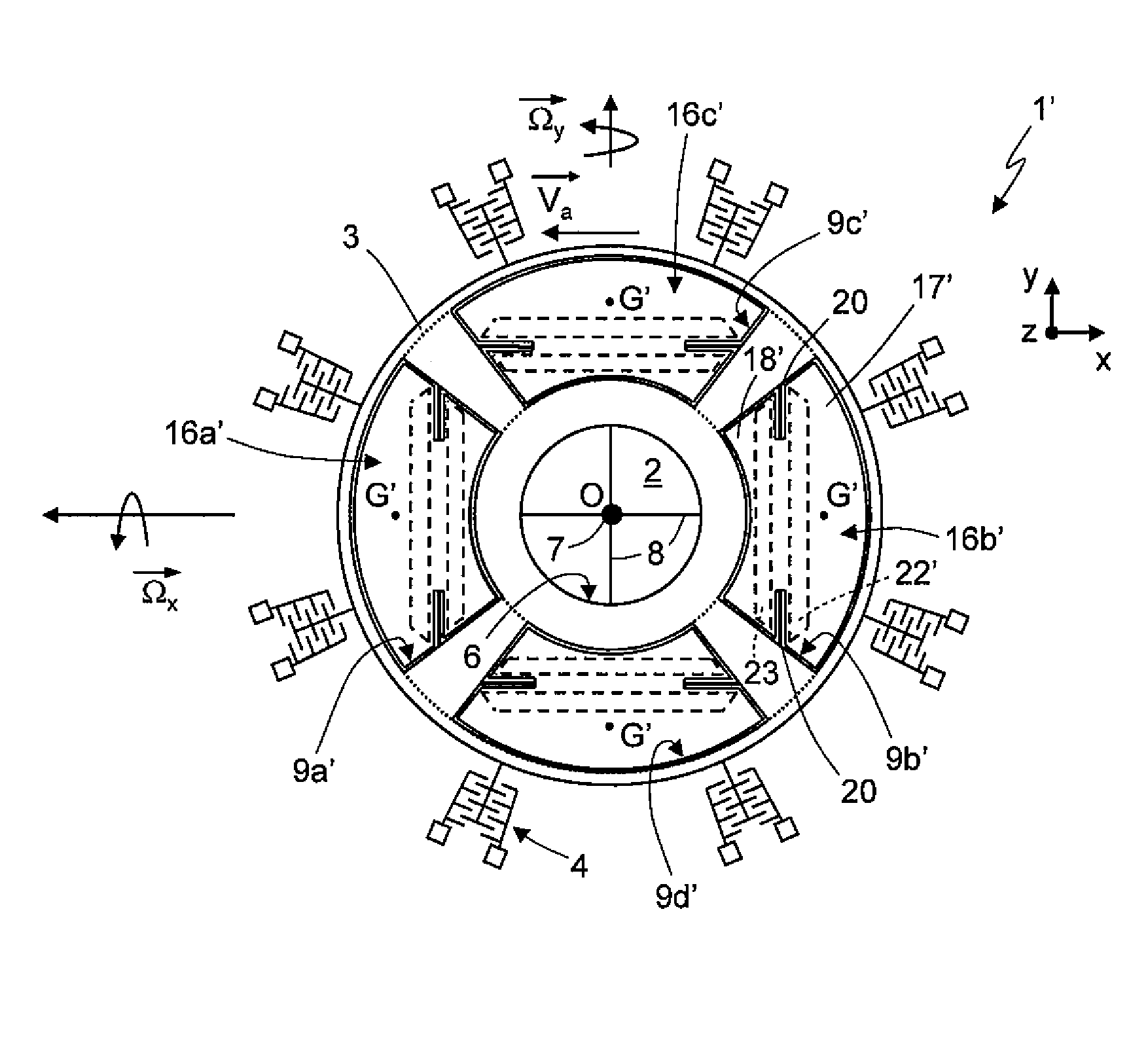
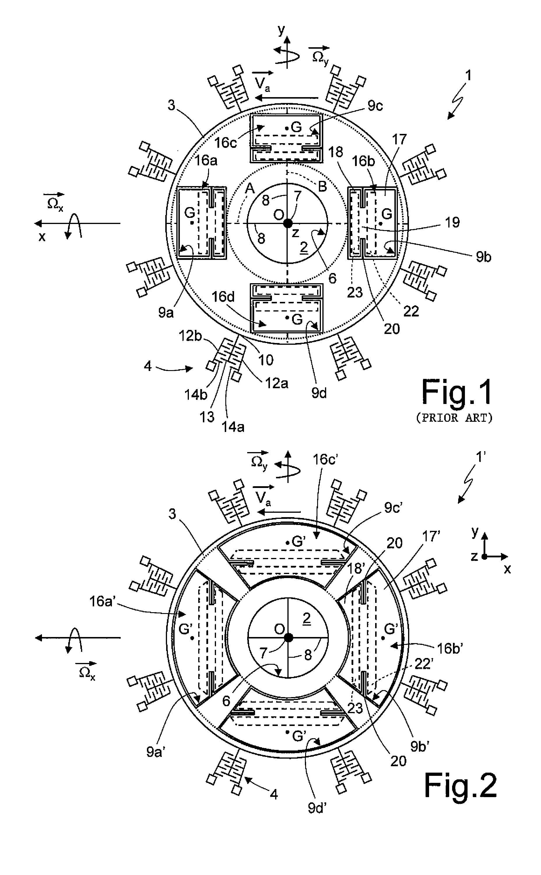
[0030]As shown in FIG. 2 (and in the enlarged view of FIG. 3), wherein same reference numerals are used to refer to the same elements shown in FIG. 1, the microelectromechanical sensor, here denoted with 1′, differs from the sensor described with reference to FIG. 1 for a different shape of the through-openings made in the driving mass 3, here denoted with 9a′-9d′, and of the corresponding sensing masses, here denoted with 16a′-16d′.

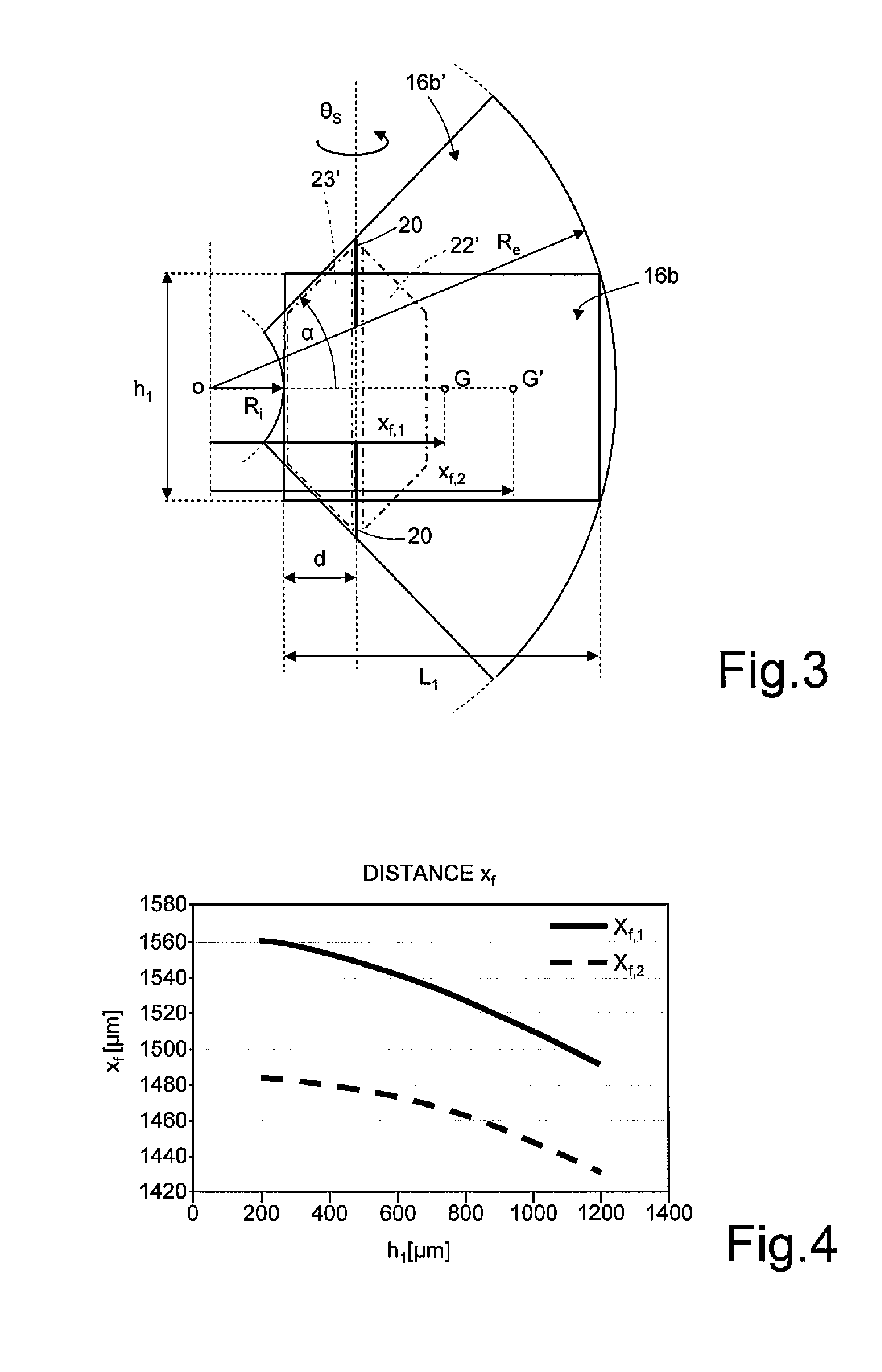
[0031]In detail, each of the through-openings 9a′-9d′ has in the plane of the sensor xy the shape of a radial annulus sector whose inner radius Ri can be as small as the inner radius of the driving mass 3 and outer radius Re can be as large as the outer radius of the same driving mass 3. This radial annulus sector has arc-shaped inner and o...


PUM


Abstract

A driving mass of an integrated microelectromechanical structure is moved with a rotary motion about an axis of rotation, and a sensing mass is connected to the driving mass via elastic supporting elements so as to perform a detection movement in the presence of an external stress. The driving mass is anchored to an anchorage arranged along the axis of rotation by elastic anchorage elements. An opening is provided within the driving mass and the sensing mass is arranged within the opening. The elastic supporting and anchorage elements render the sensing mass fixed to the driving mass in the rotary motion, and substantially decoupled from the driving mass in the detection movement. The detection movement is a rotation about an axis lying in a plane. The sensing mass has, in plan view, a non-rectangular shape; in particular, the sensing mass has a radial geometry and, in plan view, the overall shape of a radial annulus sector.

Description

BACKGROUND[0001]1. Technical Field[0002]The present invention relates to a high sensitivity microelectromechanical sensor having a rotary driving motion. In particular, in the following description reference will be made to a gyroscope (whether uniaxial or biaxial), which can possibly operate as an accelerometer (whether uniaxial or biaxial).[0003]2. Description of the Related Art[0004]As is known, microprocessing techniques enable formation of microelectromechanical structures or systems (the so-called MEMS) within layers of semiconductor material, which have been deposited (for example, in the case of a layer of polycrystalline silicon) or grown (for example, in the case of an epitaxial layer) on top of sacrificial layers, which are removed by chemical etching. Inertial sensors, accelerometers and gyroscopes obtained with this technology are encountering an increasing success, for example in the automotive field, in inertial navigation, or in the sector of portable devices.[0005]I...

Claims


Application Information

Patent Timeline
Patent Type & Authority Applications(United States)
IPC IPC(8): G01C19/56
CPCG01C19/5712G01P15/18G01P15/14G01P15/125G01P2015/0828
Inventor CORONATO, LUCALUDOVICO, ALESSANDRO BALZELLIZERBINI, SARAH
Owner STMICROELECTRONICS SRL
Why Eureka
Try Eureka