
Tear seal moveable ground jaw for a tubing sealer

a ground jaw and sealer technology, applied in the field of tubing sealers, can solve the problems of difficult to achieve the effects of preventing heat buildup, reducing the risk of injury,

Active Publication Date: 2009-04-23
VANTE
View PDF4 Cites 11 Cited by
  • Summary
  • Abstract
  • Description
  • Claims
  • Application Information

AI Technical Summary

Benefits of technology

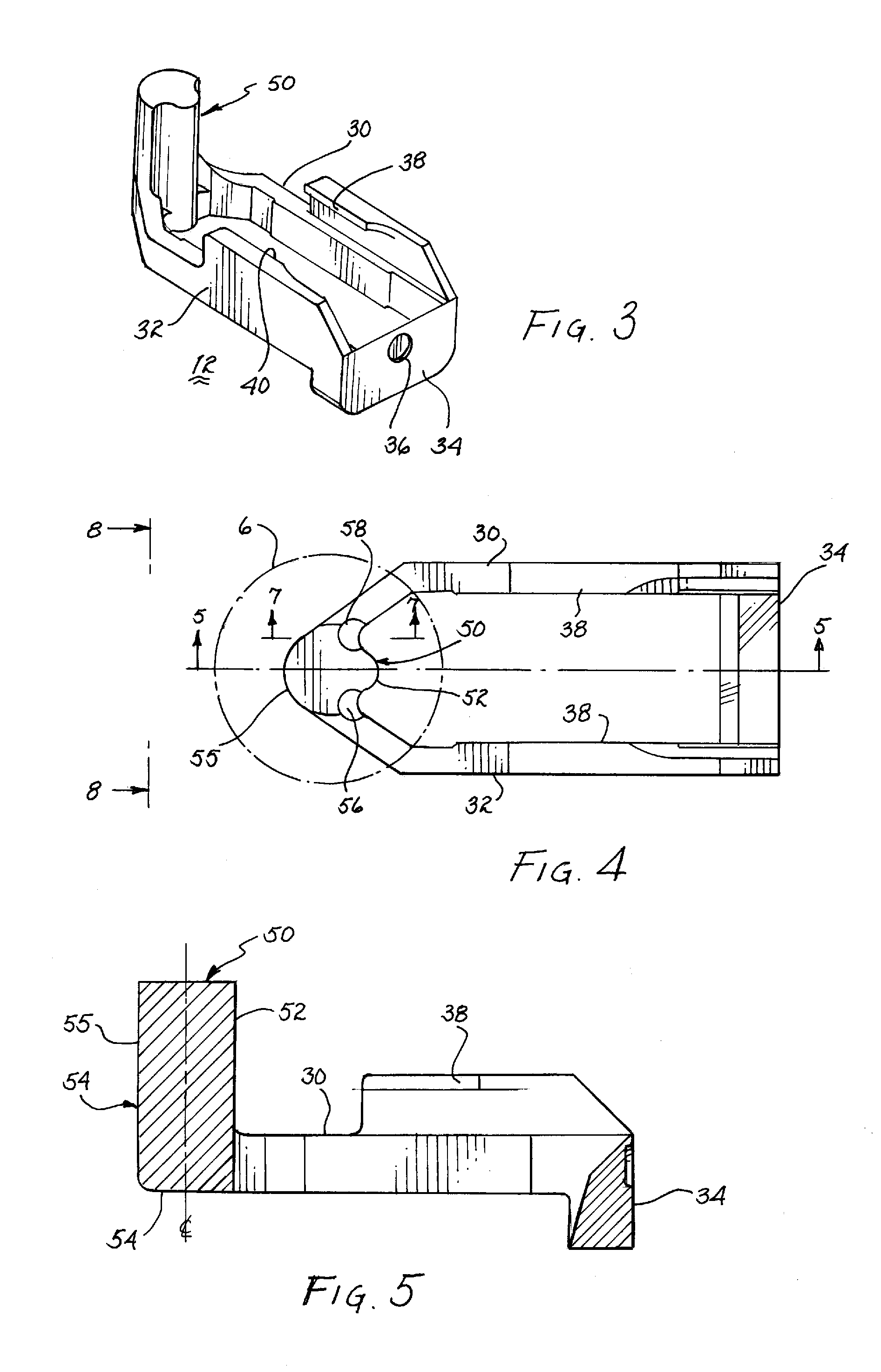
[0013]A fixed jaw and a moveable ground jaw, whether mounted in a hand held sealer or a desk mounted sealer, compresses, heats, elongates, spreads and forms a weld across liquid filled tubing placed therebetween. The fixed jaw transmits RF energy to the moveable ground jaw to perform the function of heating the tubing placed therebetween. The fixed jaw is generally an elongated metallic element or strip having a flat or planar surface coming in contact with the tubing. A pair of ceramic inserts are disposed on opposed sides of the strip and extend laterally and away from the plane of the planar surface. The moveable ground jaw is relatively massive to serve as a heat sink to dissipate and prevent heat buildup and is configured to have significant surface area for convective cooling and radiating the heat into the environment. The configuration of the moveable ground jaw coming into contact with the tubing is primarily responsible for effecting compression, focusing RF energy, elongating and welding opposed sidewalls of the tubing with one another. Furthermore, the configuration of the moveable ground jaw has a primary influence on the integrity of the weld or seal formed across the tubing and on the ease and uniformity with which adjacent segments of tubing can be torn apart across the weld. Through much experimentation over a period of years it has been learned that a cylindrical moveable ground jaw surface having a longitudinal axis aligned with the planar surface of the strip on the positive jaw will form a seal that exceeds the parameters of integrity, segment separation and suitability along the weld, while requiring a minimum amount of energy.

Problems solved by technology

However, the means for testing, typing, storing and preserving the collected blood requires relatively sophisticated techniques and equipment to minimize loss from contamination or spoilage.
These persons are often physically handicapped by the natural processes of aging, by arthritis or by previous injuries.
The major difficulty encountered during development of each of these sealers is that of controlling the melting of the tubing to form a strong seal between adjacent segments capable of withstanding centrifuging pressures imposed upon the liquid within the tubing segments without compromising the seal.
Secondly, the serial sealed segments of liquid filled tubing must be easily separated from one another.

Method used


Image

  • Tear seal moveable ground jaw for a tubing sealer
  • Tear seal moveable ground jaw for a tubing sealer
  • Tear seal moveable ground jaw for a tubing sealer

Examples


Embodiment Construction

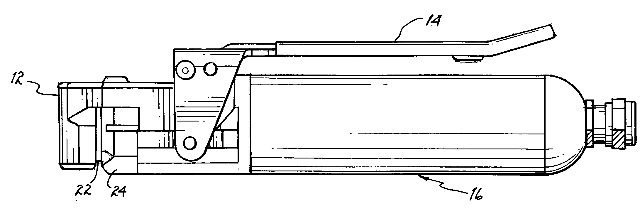
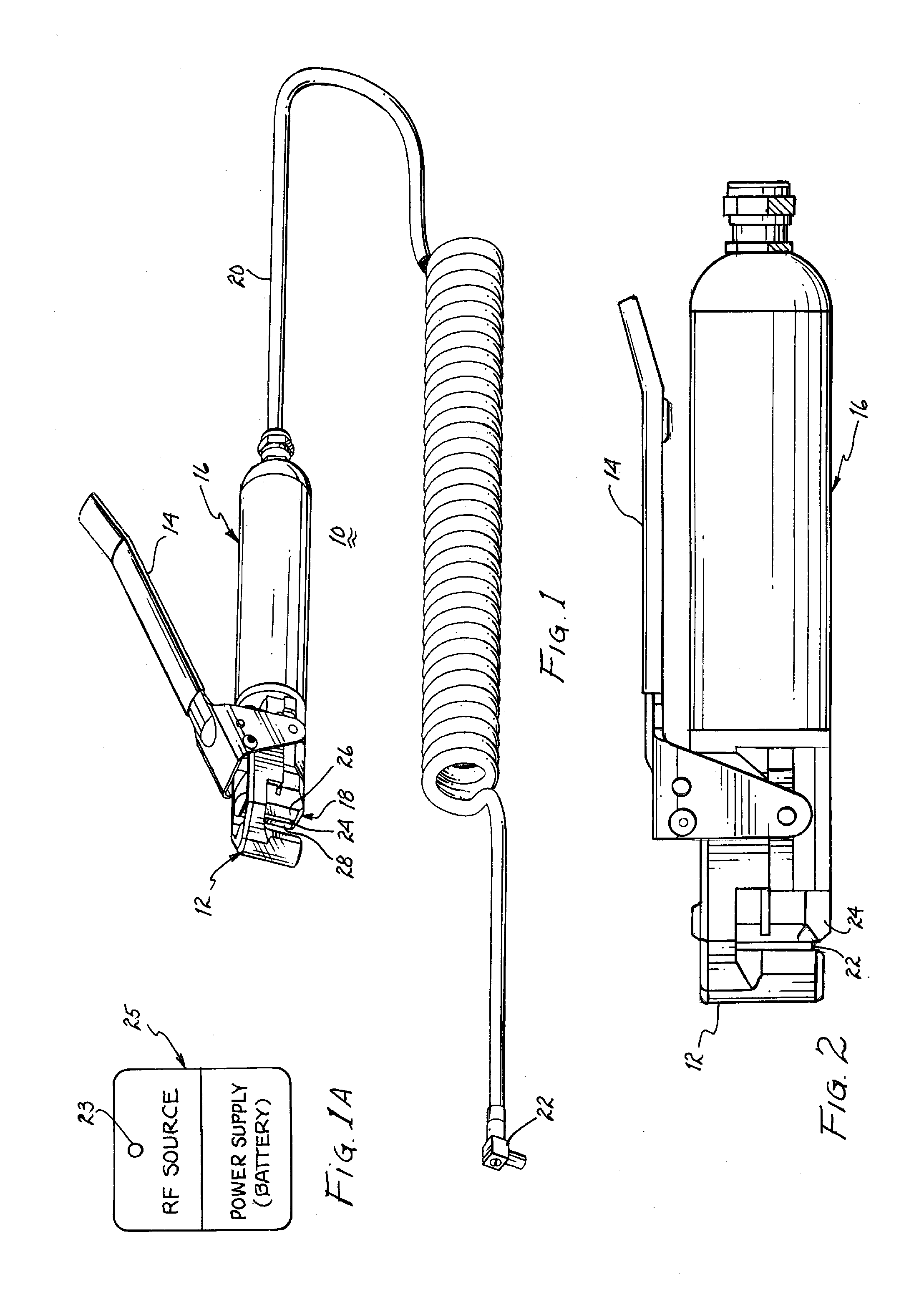
[0036]FIG. 1 illustrates a hand held sealer 10 embodying a moveable ground jaw 12 upon pivotal movement of handle 14 toward body 16. The body includes electronic circuitry for controlling / regulating RF energy to be transmitted from fixed jaw 18 to moveable ground jaw 12. Additionally, the body includes mechanical elements responsive to movement of handle 14 for drawing moveable ground jaw 12 toward fixed jaw 18. An electrical conductor 20 includes a plug 22 for connection to a socket 23 in a housing 25, as shown in FIG. 1A. The housing includes a source electrical power, usually a rechargeable battery and a source for generating RF energy. It is to be understood that the source for generating RF energy could be housed in body 16.

[0037]As particularly shown in FIG. 2, upon movement of handle 14 toward body 16, moveable ground jaw 12 is proximate RF conducting planar strip 24 of fixed jaw 18. Typically, the strip is bracketed between ceramic inserts 26, 28. The surfaces of the ceramic...


PUM

PropertyMeasurementUnit
Timeaaaaaaaaaa
Timeaaaaaaaaaa
Pressureaaaaaaaaaa

Abstract

Tubing sealers, whether hand held or desk mounted, heat seal liquid filled plastic tubing on command to develop sealed liquid filled easily separable segments serially attached to one another. The sealer generates a source of RF energy to heat seal the plastic tubing on placement of the tubing between a fixed jaw and a tubing compressing moveable ground jaw. The moveable ground jaw serves as a heat sink to dissipate heat and prevents a heat buildup during rapid repetitive operation of the sealer. The configuration of the moveable ground jaw coming in contact with the tubing primarily, but in combination with the degree of compression of the tubing and the RF power applied, controls both the integrity of the seal and the ease with which the sealed segments of tubing can be separated from one another.

Description

BACKGROUND OF THE INVENTION[0001]1. Field of the Invention[0002]The present invention relates to tubing sealers, and more particularly, to the configuration of the movable ground jaw cooperating with a fixed jaw to form a tear seal across liquid filled plastic tubing.[0003]2. Description of the Prior Art[0004]There is a continuing existing need for blood donors in order to meet the day-to-day hospital demand for blood. The collection of blood from donors is a critical function performed in all towns, cities and metropolitan areas as the need for fresh blood and plasma by hospitals never diminishes. During periods of national emergency, the need may be significantly greater. Consequently, various private and government related blood collection centers have been established at permanent locations and mobile blood collection units are employed to service remote areas or to obtain blood from donors at specific high density locations, such as shopping centers, factories, office buildings...

Claims


Application Information

Patent Timeline
IPC IPC(8): B29C65/02H05B6/62H05B6/50
CPCB29C59/007B29C66/5221B29C65/8246B29C66/7352B29C66/81811B29C66/81831B29C66/861B29C66/8618B29C66/949B29C2035/0861B29L2031/7148H05B6/50H05B6/62B29C65/04B29C65/00B29C66/8322B29L2023/007B29C66/1122B29C66/4312B29C66/81422B29C66/81423B29C66/857B29C66/8614B29C66/8416B29C66/8414B29C66/735B29C66/919
Inventor SUMEER, TULSIE P.WRIGHT, DOUGLAS F.SHAH, SHILPIN
Owner VANTE
Learn More