Quartz crystal device for surface mounting

a crystal device and surface mounting technology, applied in piezoelectric/electrostrictive device details, piezoelectric/electrostrictive/magnetostrictive devices, piezoelectric/electrostriction/magnetostriction machines, etc., can solve the problem of insufficient anti-shock characteristics of above described crystal units, and the fixing strength against shocks does not substantially improve, and the thickness is large. , the effect of reducing the separation distan

Inactive Publication Date: 2009-04-23
NIHON DEMPA KOGYO CO LTD
View PDF15 Cites 14 Cited by
  • Summary
  • Abstract
  • Description
  • Claims
  • Application Information

AI Technical Summary

Benefits of technology

[0030]In such a configuration, when the width of the crystal blank is small, the crystal blank can be fixed to the holding terminals in a region near the center of the holding terminals, that is, the first region having a small thickness. On the other hand, when the width of the crystal blank is large, the crystal blank can be fixed to the holding terminals in a region near outside the holding terminal, that is, the second region having a large thickness. Therefore, various types of crystal blank having different widths can be accommodated in the container body having a standardized size in the same way as in the related arts and productivity can be improved. When the ...

Problems solved by technology

However, the above described conventional surface-mount crystal unit has a problem that as the miniaturization advances, the vibration frequency changes when a shock is applied.
That is, the above described crystal unit has an insufficient anti-sh...

Method used


Image

  • Quartz crystal device for surface mounting
  • Quartz crystal device for surface mounting
  • Quartz crystal device for surface mounting

Examples


first embodiment

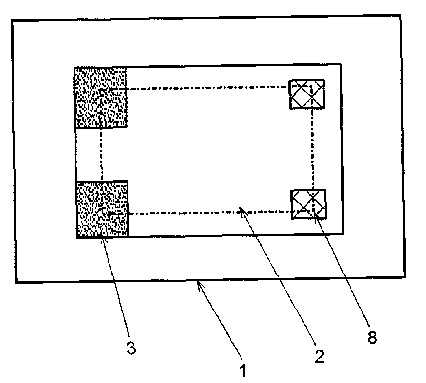
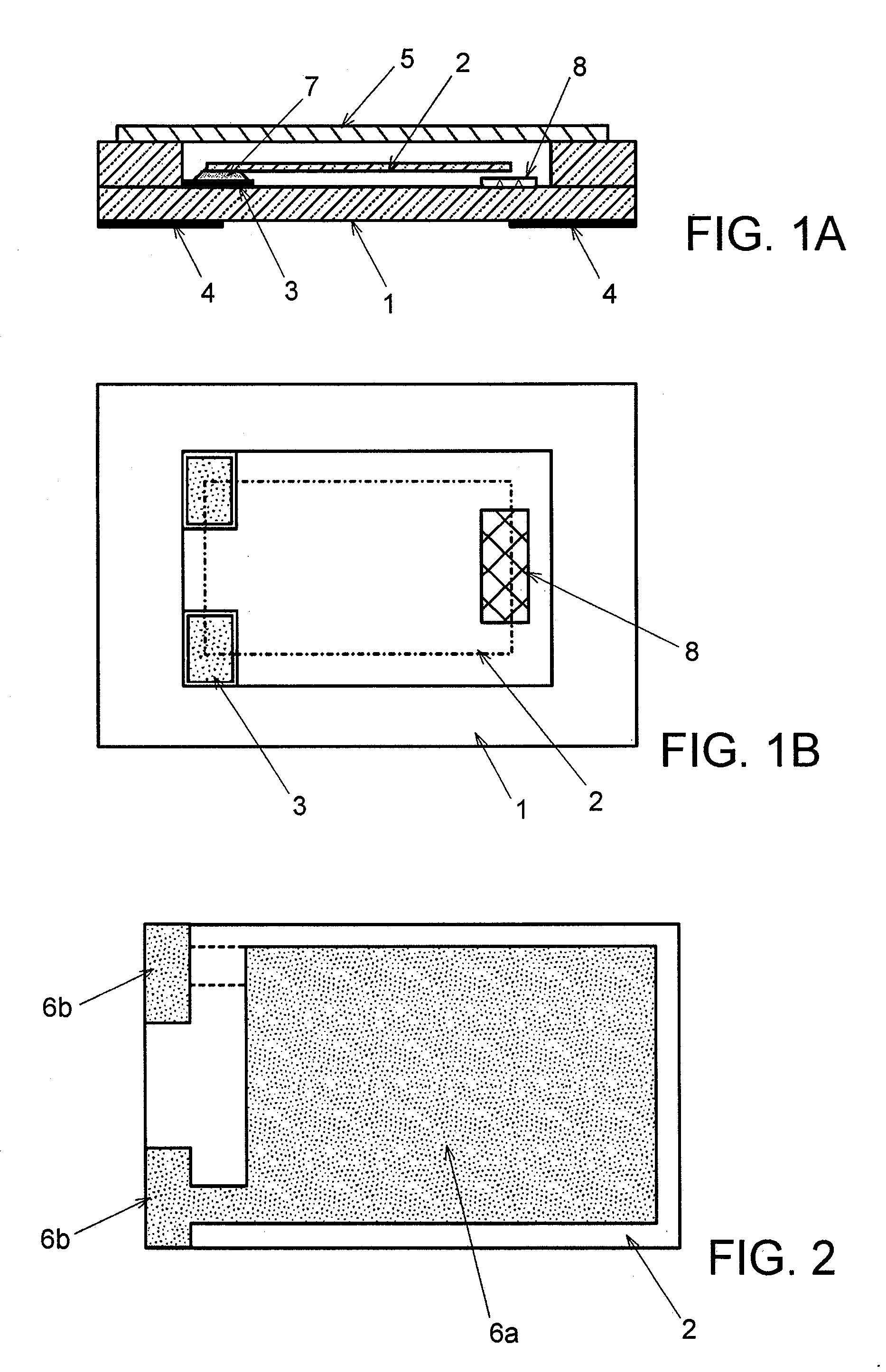
[0042]In FIG. 5 showing a surface-mount crystal unit, which is a quartz crystal device according to the present invention, the same components as those in aforementioned FIGS. 1A, 1B and 2 are assigned the same reference numerals and redundant explanations will be simplified or omitted.

[0043]The crystal unit shown in FIG. 5 is similar to those shown in FIGS. 1A, 1B and 2, but different from those in FIGS. 1A, 1B and 2 in the number and arrangement of pillow members 8. FIG. 5 shows the crystal unit with a metal cover removed for explanation.

[0044]This crystal unit is obtained by fixing both sides of one end of crystal blank 2, to which lead-out electrodes 6b extend outward from excitation electrode 6a, to holding terminals 3 provided on an inner bottom surface of a recess of container body 1 by means of conductive adhesive 7 and accommodating crystal blank 2 in the recess. A free end of crystal blank 2 contacts pillow members 8 provided on the inner bottom surface of the recess, or i...

second embodiment

[0052]FIG. 7 shows holding terminals 3 used for the surface-mount crystal unit which is the quartz crystal device according to the present invention. In FIG. 7, the same components as those in FIGS. 1A, 1B, 2 and 4 above are assigned the same reference numerals and redundant explanations will be simplified or omitted.

[0053]This crystal unit is similar to the aforementioned one, but is different in the shape of holding terminals 3 that hold crystal blank 2.

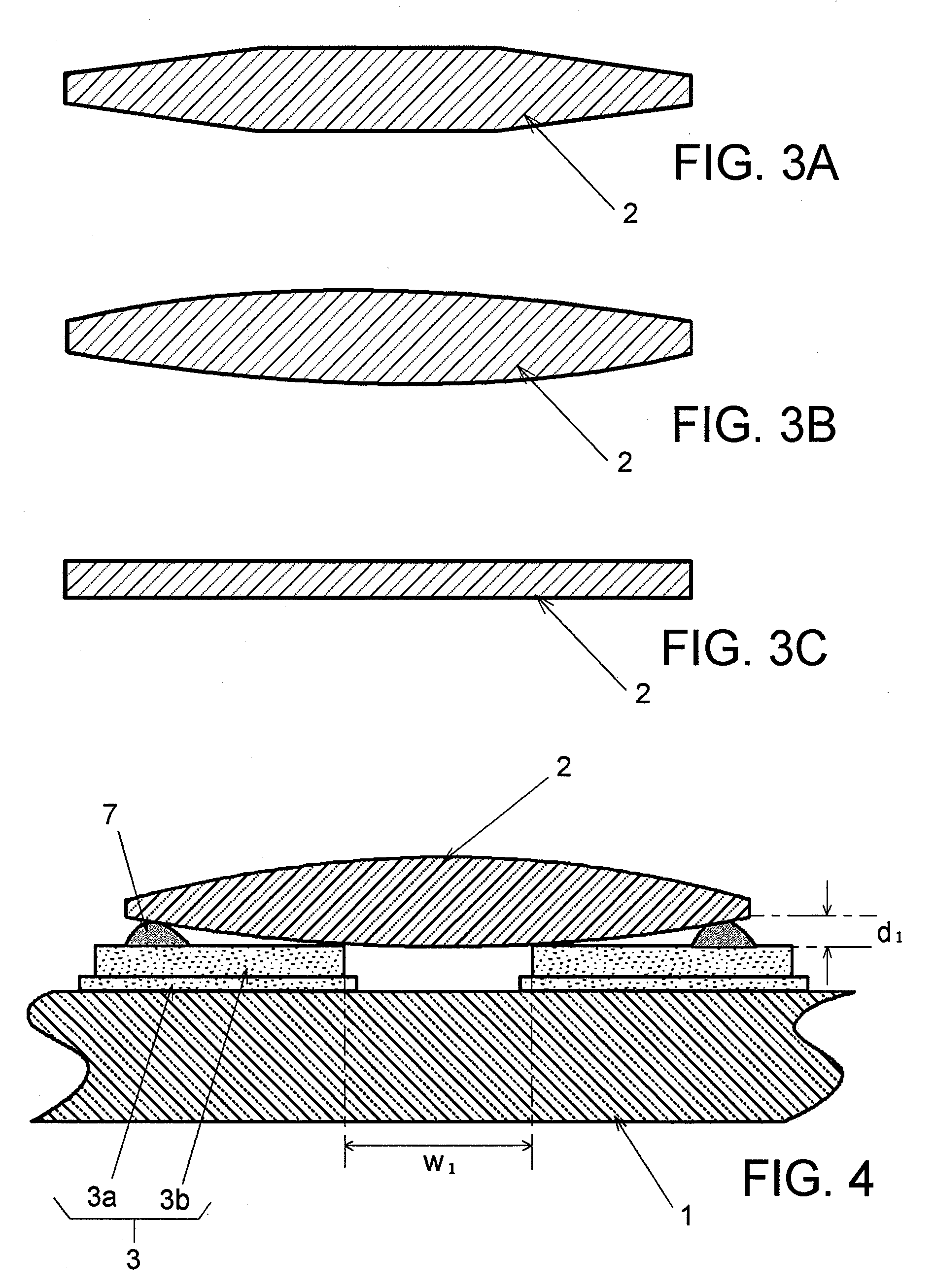
[0054]As described above, this crystal unit is obtained by fixing both sides of one end of crystal blank 2, to which lead-out electrodes 6b extend outward from excitation electrodes 6a, to holding terminals 3 provided on the inner bottom surface of container body 1 having outside terminals 4 by means of conductive adhesive 7 and providing coverage and hermetic sealing with metal cover 5. As crystal blank 2, as shown in FIGS. 3A, 3B and 3C, one made into a bevel shape or convex shape through edge dressing and formed into a convex sh...


PUM


Abstract

The quartz crystal device includes a container body having: a recess; a pair of holding terminals formed on an inner bottom surface of the recess; and a crystal blank, both principal surfaces of which are provided with excitation electrodes with lead-out electrodes extending from the pair of excitation electrodes toward both sides of one end of the crystal blank. Both sides of one end of the crystal blank are fixed to the holding terminals using a conductive adhesive. Pillow members are provided on the inner bottom surface of the recess at positions corresponding to corners on both sides of the other end of the crystal blank, and the two pillow members are independent of each other. Alternatively, each holding terminal includes a first region formed near the facing holding terminal and a second region having a greater thickness than the first region formed far from the facing holding terminal.

Description

BACKGROUND OF THE INVENTION[0001]1. Field of the Invention[0002]The present invention relates to a quartz crystal device having a configuration in which a quartz crystal blank is hermetically sealed in a container, and more particularly, to a quartz crystal device for surface mounting capable of normally operating even when the device receives a mechanical shock and maintaining a good vibration characteristic thereof.[0003]2. Description of the Related Arts[0004]Quartz crystal units having a quartz crystal blank hermetically sealed in a container, and quartz crystal oscillators, in which such a crystal unit and an IC (integrated circuit) chip having a circuit using the crystal unit are integrated, are generically called “quartz crystal devices.” The quartz crystal devices are used for a variety of electronic devices. For example, surface-mount crystal units having a crystal blank hermetically encapsulated in a container are small and light, and are therefore incorporated together wi...

Claims


Application Information

Patent Timeline
IPC IPC(8): H01L41/053H01L41/04
CPCH03H9/1021
Inventor AKANE, KATSUNORIHARADA, MASAKAZU
Owner NIHON DEMPA KOGYO CO LTD
Why Eureka
Try Eureka