Dual moded stacked microstrip patch antenna

a patch antenna and microstrip technology, applied in the field of antennas, can solve the problems of low gain and limited efficiency of such antennas

Inactive Publication Date: 2009-04-23
MATEYCHUK DUANE N +1
View PDF2 Cites 41 Cited by
  • Summary
  • Abstract
  • Description
  • Claims
  • Application Information

AI Technical Summary

Problems solved by technology

Size constraints alone have limited the size of prior patch antennas resulting in a low gain which contributes to intermittent muting and signal outages.
In addition, satellite system antennas are used across the globe and can pose problems depending upon their geographic latitude of use.
However, despite these advantages, the efficiency of such antennas is still limited.

Method used


Image

  • Dual moded stacked microstrip patch antenna
  • Dual moded stacked microstrip patch antenna
  • Dual moded stacked microstrip patch antenna

Examples


Embodiment Construction

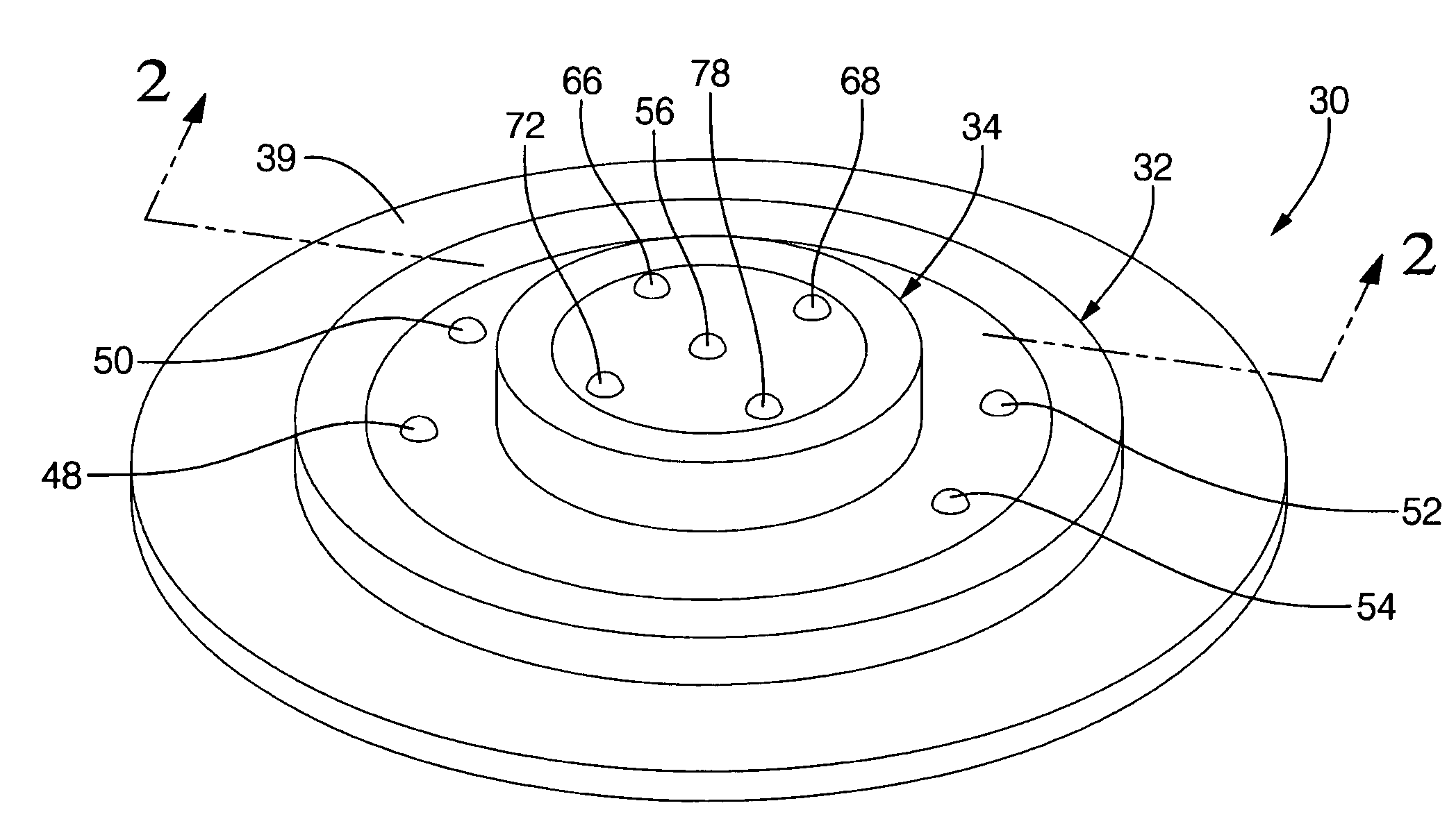
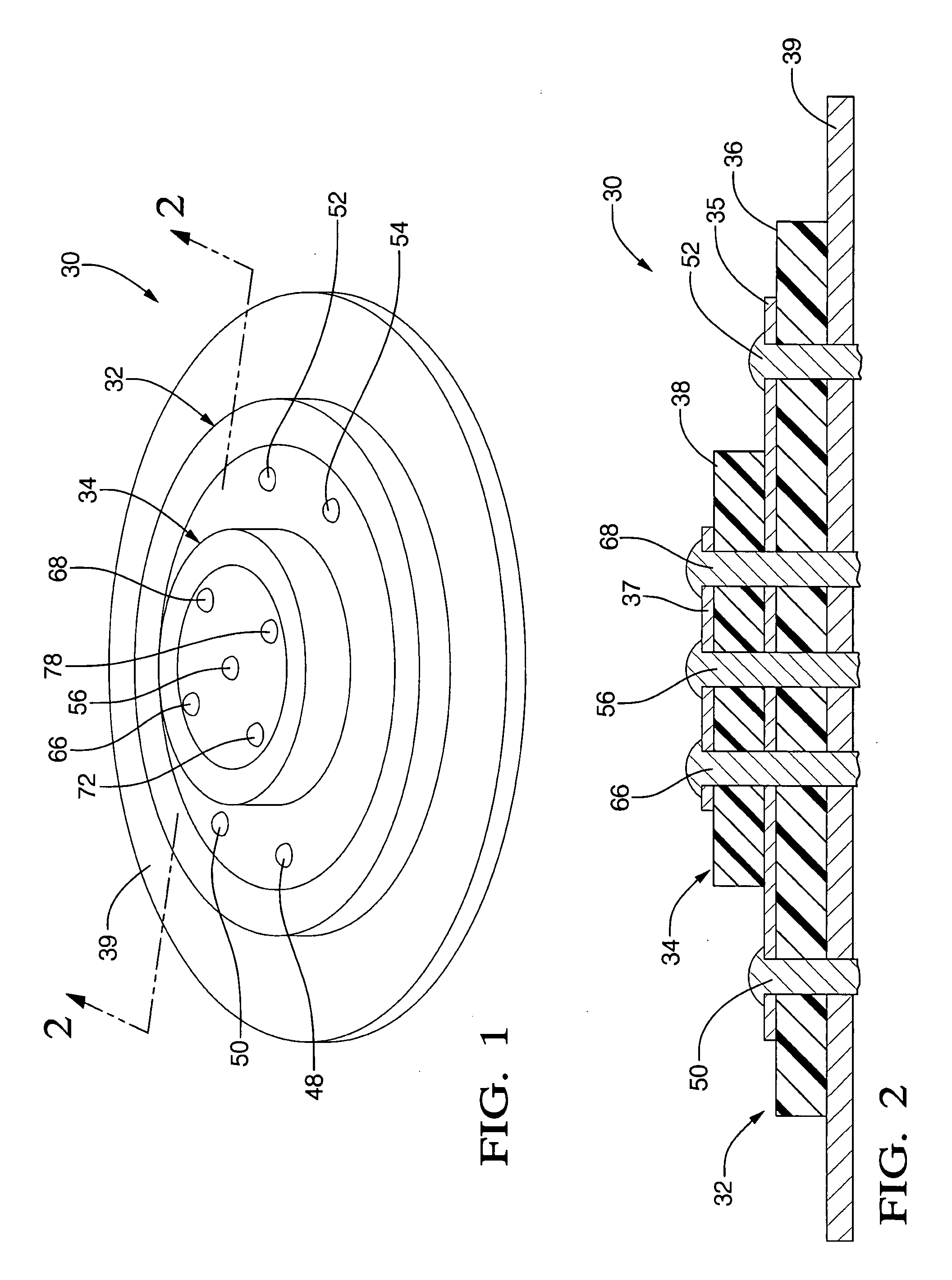
[0047]Referring now to FIGS. 1 and 2 a general view of a stacked dual mode microstrip patch antenna 30 is illustrated which includes two stacked antenna elements 32 and 34. The first or bottom antenna element 32 is a circular polarized higher order transverse magnetic mode antenna for receiving low elevation satellite and terrestrial signals. The second or upper antenna element 34 is a circular polarized lower order transverse magnetic mode circular patch antenna used to receive satellite signals. The antenna elements 32 and 34 can provide separate outputs for the terrestrial reception and the satellite reception or a combined output allowing selection of either terrestrial or satellite reception.

[0048]The second antenna element 34 is smaller in overall size than the outer dimensions of the first antenna element 32 and is stacked generally coaxially on top of and fixed to the first antenna element 32 by adhesive, over-molding, etc.

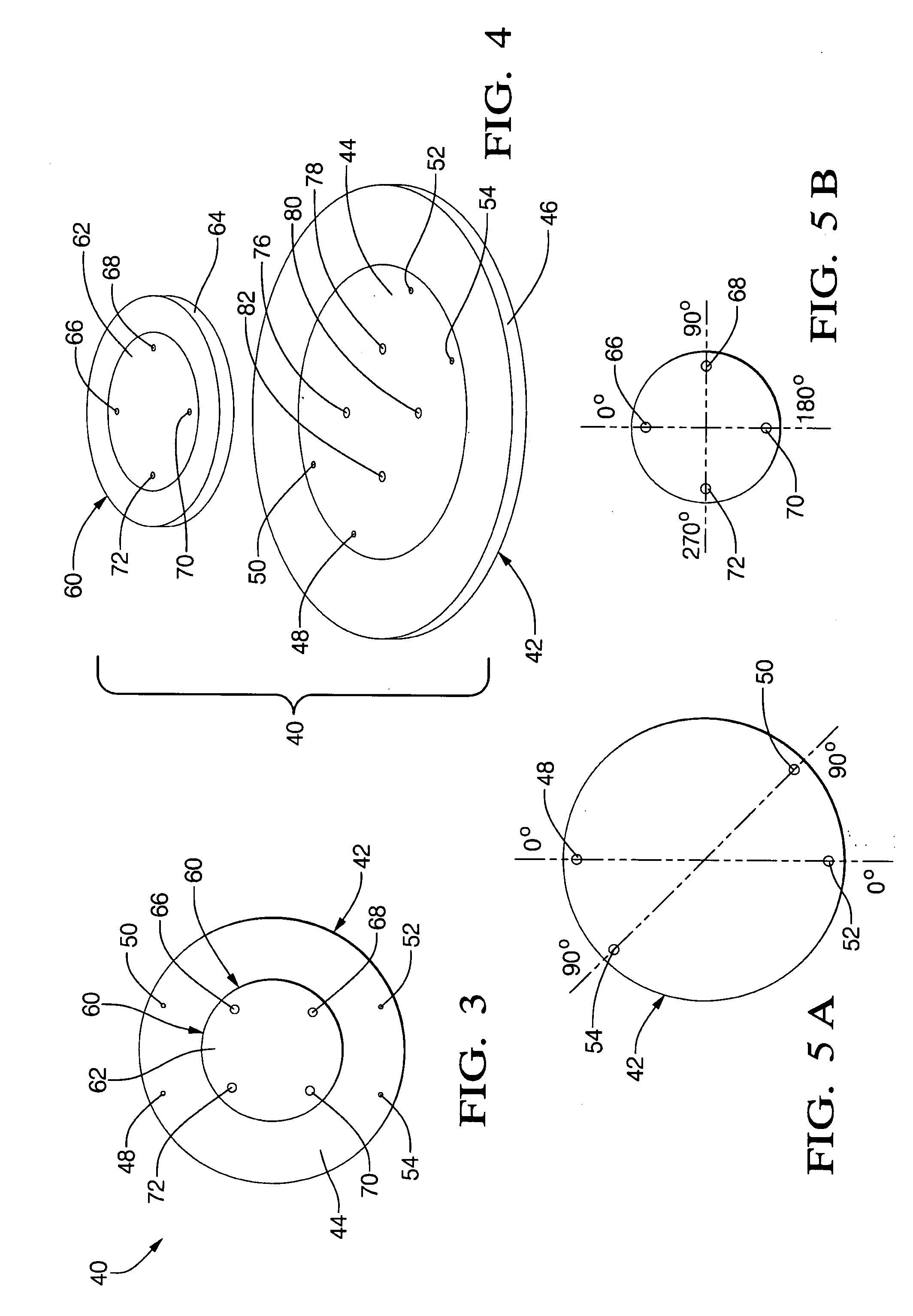
[0049]The first antenna element 32 includes a patch ...


PUM


Abstract

A dual moded stacked microstrip patch antenna includes an integrated first lower antenna element having probes excited at a higher transverse magnetic order mode and a second upper antenna element with probes excited at a lower order transverse magnetic mode. Distinct probe locations and phase offset signals are supplied to each of the probes in each of the first and second antenna elements to support the higher and lower order mode of operation.

Description

BACKGROUND OF THE INVENTION[0001]1. Field of Invention[0002]The present invention relates to an antenna mounted on a movable body which is capable of receiving both satellite and terrestrial signals.[0003]2. Description of the Related Art[0004]Satellite broadcasts of radio programs and / or GPS signals to moveable bodies, such as automobiles, have become more popular in recent years.[0005]Such satellite broadcast systems typically employ circularly polarized signals. Circularly polarized patch antennas provide this feature.[0006]A separate antenna for ground radio station broadcast signals, such as a helical or rod antenna or a vertically polarized wave antenna have been proposed for receiving such ground broadcast signals.[0007]As with any component mounted on an automobile, size, reliability, ease of mounting on non-planar surfaces, are essential features for mounting any component, and in particular, an antenna to the automobile. Size constraints alone have limited the size of prio...

Claims


Application Information

Patent Timeline
Patent Type & Authority Applications(United States)
IPC IPC(8): H01Q1/38
CPCH01Q5/40H01Q9/0414
Inventor MATEYCHUK, DUANE N.LU, JOHN Z.
Owner MATEYCHUK DUANE N
Why Eureka
Try Eureka