Inkjet recording apparatus and recording method

a recording apparatus and recording method technology, applied in the direction of printing, inking apparatus, other printing apparatus, etc., can solve the problems of large variation in back pressure variation, deterioration of image quality, and long flow channels between the recording head and the sub-tank, so as to improve the reliability of recording head ejection and satisfactory print quality

Inactive Publication Date: 2009-04-23
FUJIFILM CORP +1
View PDF11 Cites 70 Cited by
  • Summary
  • Abstract
  • Description
  • Claims
  • Application Information

AI Technical Summary

Benefits of technology

[0032]According to the present invention, a pair of liquid chambers (a first liquid chamber and a second liquid chamber) and a liquid buffer chamber are provided and by moving liquid between these liquid chambers and the liquid buffer chamber, it is possible to maintain the interiors of the first liquid chamber and the second liquid chamber at prescribed pressures, and furthermore since a prescribed pressure differential is set between the first liquid

Problems solved by technology

On the other hand, if air bubbles enter into the recording head or the ink inside the recording head (and in particular, in the vicinity of the nozzles) increases in viscosity, then there is a possibility that these factors can give rise to deterioration of the image quality, since fluctuation occurs in the droplet amount (volume) and ejection direction (direction of flight) of the ink droplets which are ejected from the respective nozzles, and nozzles suffering ejection failure occur due to blockages, and so on.
However, there are problems of the following kinds associated with the related art ink circulation technology which is described above.
Furthermore, since the ink supply system uses the liquid head differential, then it is nece

Method used


Image

  • Inkjet recording apparatus and recording method
  • Inkjet recording apparatus and recording method
  • Inkjet recording apparatus and recording method

Examples


first embodiment

[0099]FIG. 7 is an approximate diagram showing an example of the composition of an ink supply system of an inkjet recording apparatus 10A according to a first embodiment. In FIG. 7, in order to simplify the description, the ink supply system relating to only one color is depicted, but in the case of a plurality of colors, a plurality of similar compositions are provided.

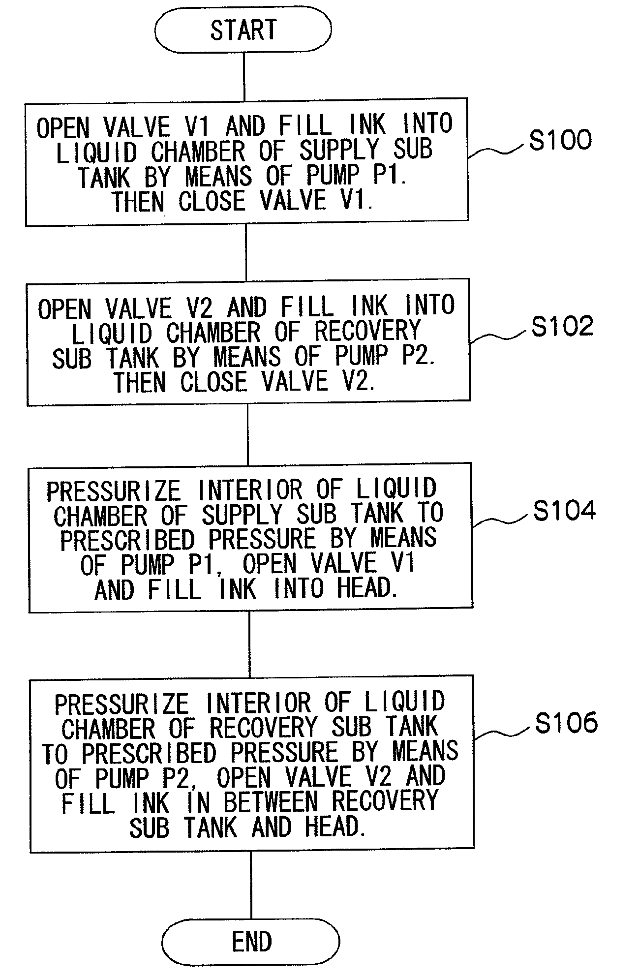
[0100]The inkjet recording apparatus 10A illustrated in FIG. 7 principally comprises: a buffer tank 110 which stores ink supplied from a main tank 100; a pair of sub tanks 120 and 130 (supply sub tank 120 and recovery sub tank 130) which are connected to the buffer tank 110; a head 50 which is connected to the sub tanks 120 and 130, pressure sensors S1 and S2 which determine the internal pressure of the sub tanks 120 and 130 respectively; and pumps P1 and P2 which adjust the interiors of the sub tanks 120 and 130 respectively to prescribed pressures by moving ink between the buffer tank 110 and the sub tanks 120 and ...

second embodiment

[0134]Next, a second embodiment of the present invention will be described. Below, portions which are common with those of the first embodiment are not explained further, and the following description centers on characteristic features of the present embodiment.

[0135]FIG. 10 is an approximate diagram illustrating an example of the composition of an ink supply system of an inkjet recording apparatus 10B according to the second embodiment. In FIG. 10, parts which are common with those in FIG. 7 are labeled with the same reference numerals.

[0136]As illustrated in FIG. 10, in the inkjet recording apparatus 10B according to the present embodiment, a deaerator 170 is provided in the first connecting flow channel 140. More specifically, a deaerator 170 is provided on the downstream side of the filter 142 (the side adjacent to the supply sub tank 120) in the first connecting flow channel 140, and to the upstream side of the junction with the second branch flow channel 160B (namely, the side...

third embodiment

[0141]Next, a third embodiment of the present invention will be described. Below, portions which are common with those of the first and the second embodiments are not explained further, and the following description centers on characteristic features of the present embodiment.

[0142]FIG. 11 is an approximate diagram showing an example of the composition of an ink supply system of an inkjet recording apparatus 10C according to a third embodiment. In FIG. 11, parts which are common with those in FIGS. 7 and 10 are labeled with the same reference numeral.

[0143]As illustrated in FIG. 11, a first expulsion flow channel 172 which connects the upper surface (vertical upper portion) of the liquid chamber 124 of the supply sub tank 120 with the liquid chamber 134 of the recovery sub tank 130 and a second expulsion flow channel 174 which connects the upper surface (vertical upper portion) of the liquid chamber 134 of the recovery sub tank 130 with the buffer tank 110 are provided in the inkjet...


PUM


Abstract

An inkjet recording apparatus has: a recording head of an inkjet type having a liquid ejection surface where a plurality of nozzles which eject liquid are arranged, a supply port which supplies the liquid to an internal flow channel connected to the plurality of nozzles, and an outlet port which is connected to the supply port via the internal flow channel and through which the liquid in the internal flow channel is expelled; a first liquid chamber which is connected to the supply port of the recording head via a first external flow channel; a second liquid chamber which is connected to the outlet port of the recording head via a second external flow channel; a liquid buffer chamber which stores the liquid supplied from a liquid supply source; a first connecting flow channel which connects the first liquid chamber to the liquid buffer chamber; a second connecting flow channel which connects the second liquid chamber to the liquid buffer chamber; a first pressure determination device which determines an internal pressure of the first liquid chamber; a second pressure determination device which determines an internal pressure of the second liquid chamber; a liquid movement device which moves the liquid between the first liquid chamber, the second liquid chamber and the liquid buffer chamber; and a pressure control device which controls the liquid movement device in accordance with determination results of the first pressure determination device and the second pressure determination device in such a manner that interiors of the first liquid chamber and the second liquid chamber respectively assume prescribed pressures, wherein the pressure control device controls the liquid movement device so as to adjust the internal pressures of the first liquid chamber and the second liquid chamber in such a manner that a prescribed pressure differential between the internal pressures of the first liquid chamber and the second liquid chamber is produced and a prescribed back pressure is applied to the liquid inside the plurality of nozzles of the recording head.

Description

BACKGROUND OF THE INVENTION[0001]1. Field of the Invention[0002]The present invention relates to an inkjet recording apparatus and a recording method, and more particularly, to an inkjet recording apparatus and an inkjet recording method whereby continuous circulation of liquid can be achieved while maintaining the back pressure in a recording head of an inkjet type.[0003]2. Description of the Related Art[0004]The inkjet recording apparatus comprises a recording head of an inkjet type (an inkjet head, hereinafter simply called “head”) which has a plurality of nozzles, and records an image by ejecting ink droplets respectively from the nozzles. Such apparatuses are used widely from commercial to industrial applications, due to their low operating noise, low running costs, and their capacity to record high quality images onto recording media of many various types. The ink ejection method used in the recording head may be a piezoelectric method in which ink droplets are ejected from no...

Claims


Application Information

Patent Timeline
IPC IPC(8): B41J29/38B41J2/175
CPCB41J2/175B41J2/17553B41J2/17513B41J2002/14459B41J2202/12
Inventor KATADA, MASAHITOMURAKAMI, ATSUSHI
Owner FUJIFILM CORP
Why Eureka
Try Eureka