High Speed Photographic Device, Method For Controlling High Speed Photographic Device, and Computer Program

Inactive Publication Date: 2009-04-23
KEYENCE
View PDF3 Cites 7 Cited by
  • Summary
  • Abstract
  • Description
  • Claims
  • Application Information

AI Technical Summary

Benefits of technology

[0011]The present invention has been made in view of the foregoing, and an object of the present invention is to provide a high speed photographic device which can display in real time a synchronous image photographed in synchronization with motion of a photographic subject which is in periodical high speed motion. Furthermore, an object of the present invention is to provide a high speed photographic device which facilitates adjustment for such a real time display. Further, an object of the present invention is to provide a high speed photographic device which can easily designate picture recording conditions of high speed picture recording.

Problems solved by technology

Generally, when a photographing frame rate is higher than a display frame rate, a photography image cannot be directly displayed in real time.
In the case of the slow reproduction, all the photography images can be observed without omission; however, the photographic subject cannot be observed in real time.
Furthermore, if the photographing frame rate becomes higher, a reproduction time becomes extremely longer as compared with a photography time; and consequently, it becomes difficult to find a photography image to be intended.
In the case of the live observation, the photographic subject can be observed in real time; however, a photography image of the photographic subject displayed on a display is a motion state with skipping some parts; and consequently, it is difficult to observe in detail.
In such a high speed photographic device, there is a problem in that adjustment of photographing conditions is not easy.
In other photographic device in which a photographic subject remains stationary, an adjustment such as focusing, exposure, and frame rates is made while confirming a photographic screen; however, in the case of the high speed photographic device, even when either the slow reproduction or the live observation is used, an adjustment of such photographing conditions is not easy.
That is, if the slow reproduction is used when the photographing conditions are adjusted, adjustment of the photographing conditions and confirmation by the slow reproduction have to be alternately repeated; and consequently, adjustment work becomes complicated and it takes time.
On the other hand, if the live observation is used, the adjustment and the observation can be performed at the same time; however, photography images with skipping some parts of the photographic subject which is in high speed motion are displayed on the display one after the other; and consequently, there is a problem in that it is difficult to perform the adjustment of the photographing conditions.
However, for example, if in the case of a high speed photographic device which monitors a production line, the production line cannot be stopped only for adjusting the photographing conditions thereof.
However, in this sort of high speed photographic device, high speed photography is intended; but synchronous photography is not intended; and therefore, the photographing frame rate cannot be finely adjusted and the synchronous photography corresponding to the motion cycle of the photographic subject cannot be performed.
For example, user-selectable photographing frame rates are discrete values such as 60, 125, 250, 500, 1000, 2000, 4000, 8000, 16000, and 32000 fps; and since its option is small, it is not possible to photograph the photographic subject in synchronization with motion of a fan which rotates at 32 Hz, for example, and to perform focus adjustment.
However, in the case where the synchronous photography is performed using the stroboscope, even when the stroboscopic illuminator is not required as exposure conditions of a camera, the stroboscopic illuminator has to be used; and therefore, there is a problem in that it becomes difficult to downsize an imaging device.

Method used


Image

  • High Speed Photographic Device, Method For Controlling High Speed Photographic Device, and Computer Program
  • High Speed Photographic Device, Method For Controlling High Speed Photographic Device, and Computer Program
  • High Speed Photographic Device, Method For Controlling High Speed Photographic Device, and Computer Program

Examples


embodiment 1

Preferred Embodiment 1

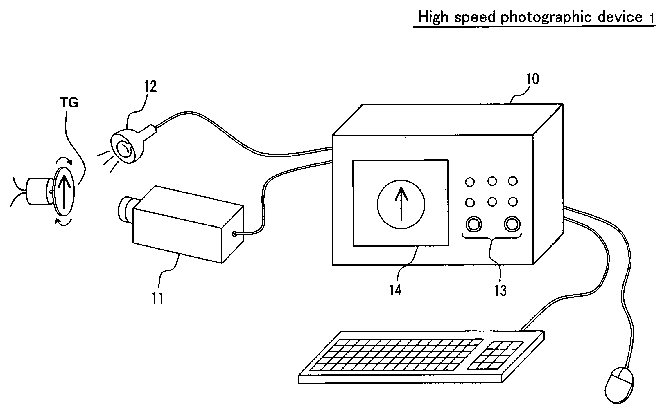
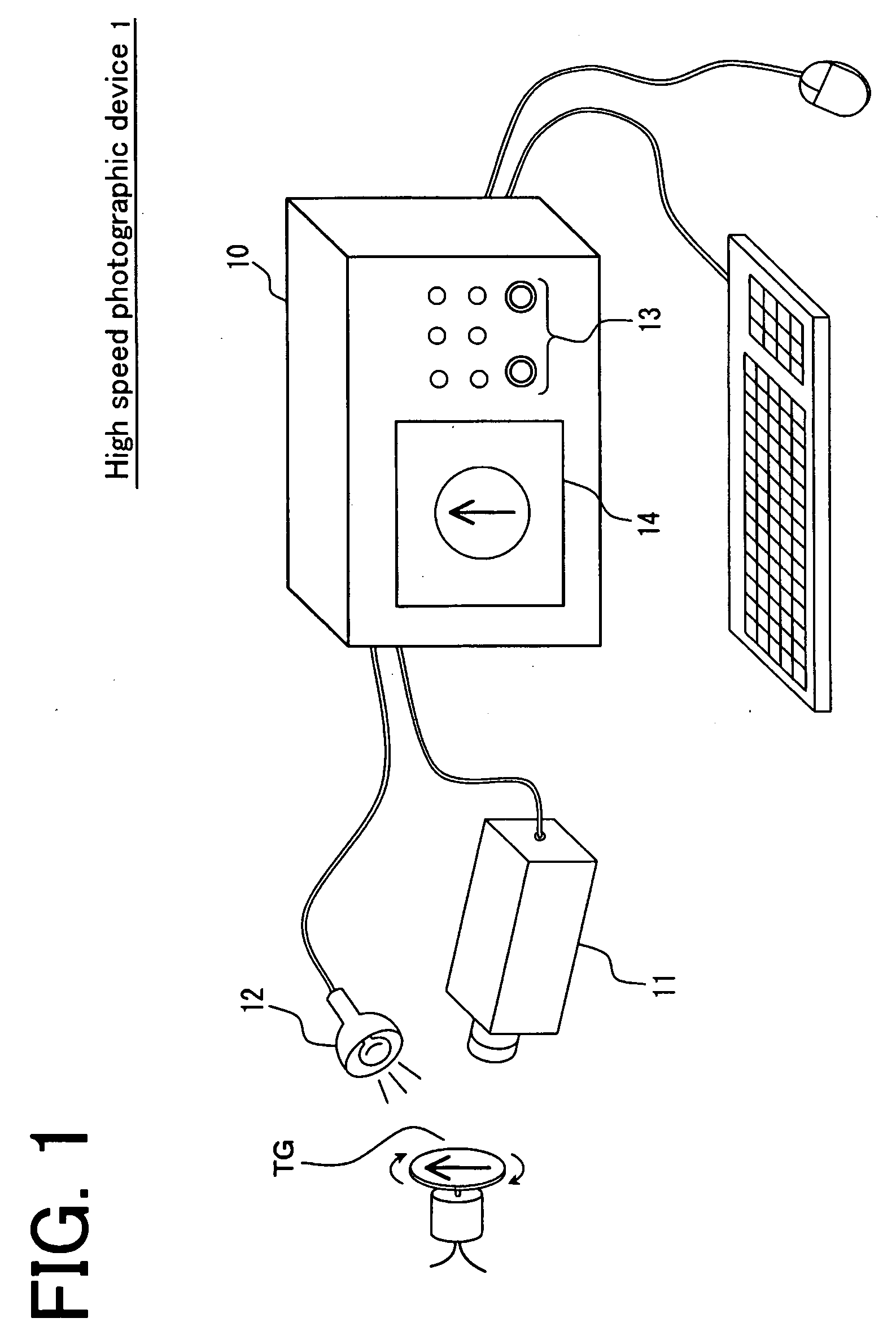
[0034]FIG. 1 is a view showing a configuration example of a high speed photographic device according to a preferred embodiment 1 of the present invention. The high speed photographic device 1 is composed of a camera 11 which is for photographing a photographic subject TG and a photographic control device 10 which controls the camera 11. The photographic control device 10 includes an operation unit 13 for which a user performs operational input, and a display unit 14 which is for displaying a photography image outputted from the camera 11.

[0035]The camera 11 is a high speed imaging unit which can photograph at a frame rate of 15 to 32000 frames per second (fps). The camera 11 incorporates a charge coupled device (CCD), a complementary metal oxide semiconductor (CMOS) image sensor, and the like which are made up of two dimensionally arranged pixels as an image sensor; and a photography image read from the image sensor is outputted to the photographic control devi...

embodiment 2

Preferred Embodiment 2

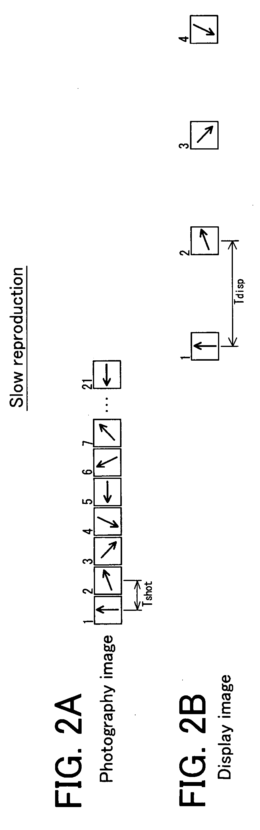
[0074]In the preferred embodiment 1, there is described the high speed photographic device which can perform a display by slow reproduction, live observation, and synchronous observation. On the other hand, in the present preferred embodiment, there will be described a high speed photographic device which can also perform a display by slow live observation in addition to the above mentioned display methods. In addition, a fundamental configuration of a high speed photographic device 1 is the same as that of the preferred embodiment 1 shown in FIGS. 1, 2A, and 2B, and their description will not be repeated.

[0075]FIGS. 11A and 11B are typical views each for explaining an example of a display method according to a preferred embodiment 2 of the present invention; and a state at the time of slow live observation is shown by setting a lateral direction as a temporal axis. In FIG. 11A, a state where frame images photographed at a photography cycle Tshot are outputted ...


PUM


Abstract

To provide a high speed photographic device which can display in real time a synchronous image photographed in synchronization with motion of a photographic subject. The high speed photographic device (1), which displays in real time a photography image which is in synchronization with a motion cycle of the photographic subject TG, includes: a synchronous cycle adjustment unit (22) which is for designating a synchronous cycle Tsync; a camera (11) which photographs the photographic subject TG at a photography cycle Tshot that is 1 / N as long as the synchronous cycle Tsync; and a display unit (14) which displays in real time the photographic subject TG by displaying the photography image of every synchronous cycle Tsync every display cycle Tdisp. The synchronous cycle adjustment unit (22) can adjust the synchronous cycle Tsync at a step width ΔTsync smaller than a visual minimum cycle, within an adjustment range which does not include less than the visual minimum cycle.

Description

BACKGROUND OF THE INVENTION[0001]1. Field of the Invention[0002]The present invention relates to a high speed photographic device, a method for controlling a high speed photographic device, and a computer program; and more particularly, the present invention relates to an improvement of a high speed photographic device which is for photographing a photographic subject which periodically repeats high speed motion and for displaying in real time a photography image in synchronization with its motion cycle.[0003]2. Description of the Related Art[0004]A high speed photographic device is a device which can photograph a photographic subject in high speed and, for example, can photograph a photographic subject at a photographing frame rate of 60 to 32000 frames per second (fps). Generally, when a photographing frame rate is higher than a display frame rate, a photography image cannot be directly displayed in real time. Therefore, in this sort of high speed photographic device, there is ado...

Claims


Application Information

Patent Timeline
IPC IPC(8): H04N5/228H04N5/335H04N5/225
CPCH04N7/183H04N5/232H04N23/63
Inventor TAKAHASHI, SHINYAYANASE, KENGO
Owner KEYENCE
Why Eureka
Try Eureka