
Optical instrument alignment system

Active Publication Date: 2009-04-23
ALCON INC
View PDF15 Cites 65 Cited by
  • Summary
  • Abstract
  • Description
  • Claims
  • Application Information

AI Technical Summary

Benefits of technology

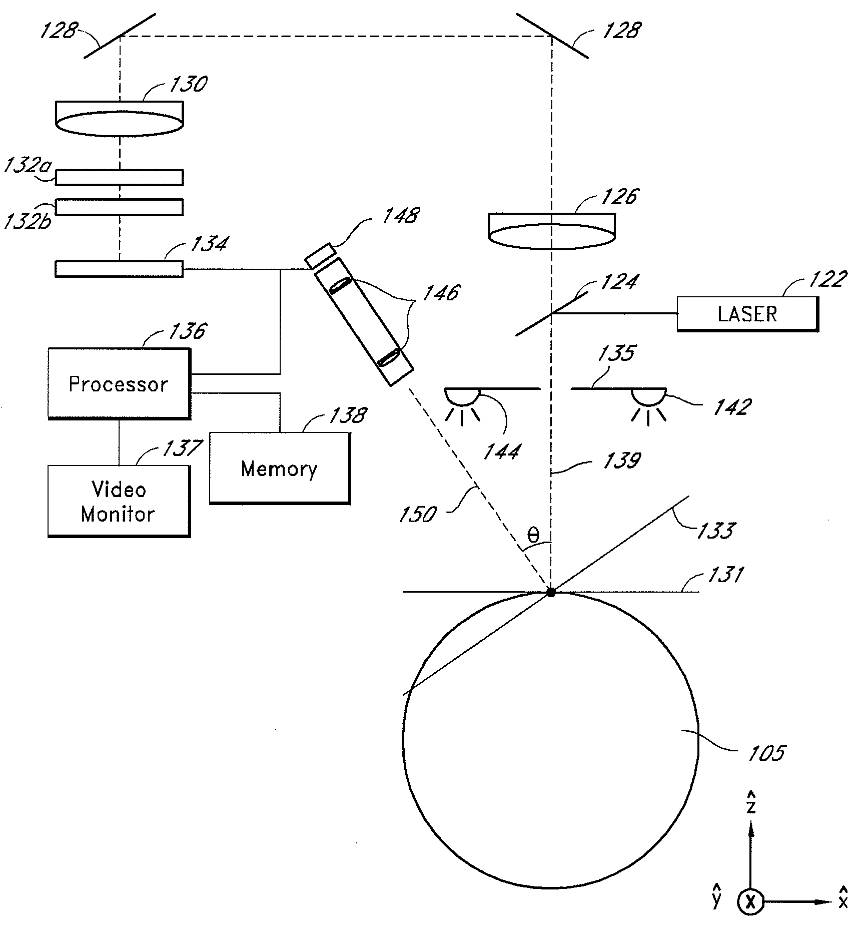
[0010]In some embodiments, a method of using an ophthalmic apparatus comprises: providing an optical instrument to perform a diagnostic measurement on the eye of a patient; providing a system for positioning the optical instrument at a desired position relative to the eye in an x-y-z three-dimensional coordinate system, the positioning system comprising a photodetector; providing curvature data about the corneal curvature of the patient's eye; causing light to be reflected from the cornea of the eye such that it impinges upon the photodetector at one or more locations; and moving the optical instrument in x, y, and z directions to position the optical instrument at the desired position relative to the eye based at least in part upon the curvature data and upon the one or more locations on the photodetector.
[0011]In some embodiments, an ophthalmic

Problems solved by technology

One important issue faced by many medical diagnosis optical systems is determining and / or maintaining a precise spatial relationship between the portion of the body undergoing diagnosis and the optical instrument.

Method used


Image

  • Optical instrument alignment system
  • Optical instrument alignment system
  • Optical instrument alignment system

Examples


Embodiment Construction

[0024]Intraocular lens (IOL) implantation surgery is one of several ophthalmic procedures that involve measurements of the refractive power of a patient's eye. In a typical IOL implantation procedure, a surgeon removes a patient's natural crystalline lens from the eye. Upon removal of the natural lens, the surgeon may take a measurement to determine the optical power of the appropriate IOL implant that will restore the eye to an emmetropic condition. This has traditionally been done by measuring preoperatively the axial length of the patient's eye using, for example, an ultrasound device and also by measuring the corneal curvature. However, in some embodiments described herein, the optical power of the appropriate IOL implant that will restore the eye to an emmetropic condition is found by direct measurement of the aphakic refractive power of the patient's eye. This refractive power measurement can be taken with any of several optical instruments, including, for example, a wavefront...


PUM


Abstract

An ophthalmic apparatus for precisely positioning an optical instrument, such as a wavefront aberrometer, in three dimensions with respect to a patient's eye. The ophthalmic apparatus may include an optical instrument directed in a first direction toward a target area to receive light therefrom and a camera directed in a second direction toward the target area to receive light therefrom, the first and second directions being non-parallel. The camera may include imaging optics to form an optical image on a photodetector array using light reflected from the target area. The ophthalmic apparatus may also include a processor configured to correlate a position of the optical image on the photodetector array with the distance between the optical instrument and the target area.

Description

CROSS-REFERENCE TO RELATED APPLICATIONS[0001]This application claims priority to U.S. Provisional Patent Application 60 / 981,146, filed on Oct. 19, 2007 and entitled “METHOD AND SYSTEM FOR OPHTHALMOLOGIC WAVEFRONT MEASUREMENT,” and to U.S. Provisional Patent Application 61 / 012,366, filed on Dec. 7, 2007 and entitled “ACCURATE FOCUS TECHNIQUE FOR AN INTRAOPERATIVE WAVEFRONT ANALYZER,” and to U.S. Provisional Patent Application 61 / 038,386, filed on Mar. 20, 2008 and entitled “OPTICAL INSTRUMENT ALIGNMENT SYSTEM,” each of which is hereby incorporated by reference herein in its entirety.BACKGROUND OF THE INVENTION[0002]1. Field of the Invention[0003]Embodiments of the invention generally relate to systems and methods for aligning an optical instrument at a desired spatial position relative to a target location such as, for example, the corneal apex of a human eye.[0004]2. Description of the Related Art[0005]Refractive surgery and other corrective procedures are commonly performed on the ...

Claims


Application Information

Patent Timeline
IPC IPC(8): A61B3/15A61B3/10
CPCA61B3/0075A61B3/154A61B3/152
Inventor MICHAELS, RICHARD J.HALL, MAXCUETO, DIEGOROWE, T. SCOTTPADRICK, THOMAS
Owner ALCON INC
Learn More