Transmitted light refractometer

a technology of transceiving light and refractometer, which is applied in the direction of material analysis through optical means, phase-affecting property measurements, instruments, etc., can solve the problems of affecting the accuracy of material analysis,

a technology of transceiving light and refractometer, which is applied in the direction of material analysis through optical means, phase-affecting property measurements, instruments, etc., can solve the problems of affecting the accuracy of material analysis,

US20090103076A1Active Publication Date: 2009-04-23FLEXIM FLEXIBLE INDMESSTECHN

Image

  • Transmitted light refractometer
  • Transmitted light refractometer
  • Transmitted light refractometer

Examples


Embodiment Construction

[0036]The invention is explained in greater detail in the following using exemplary embodiments.

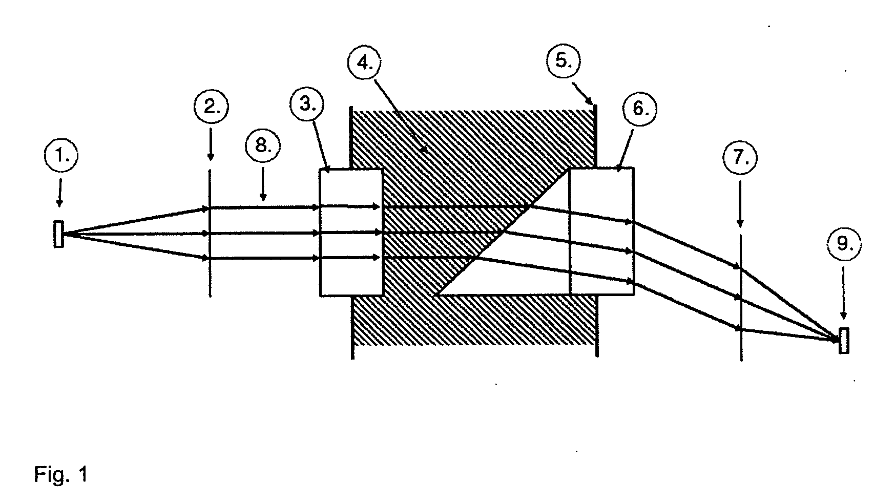
[0037]FIG. 1 depicts the principle of a transmitted light refractometer;

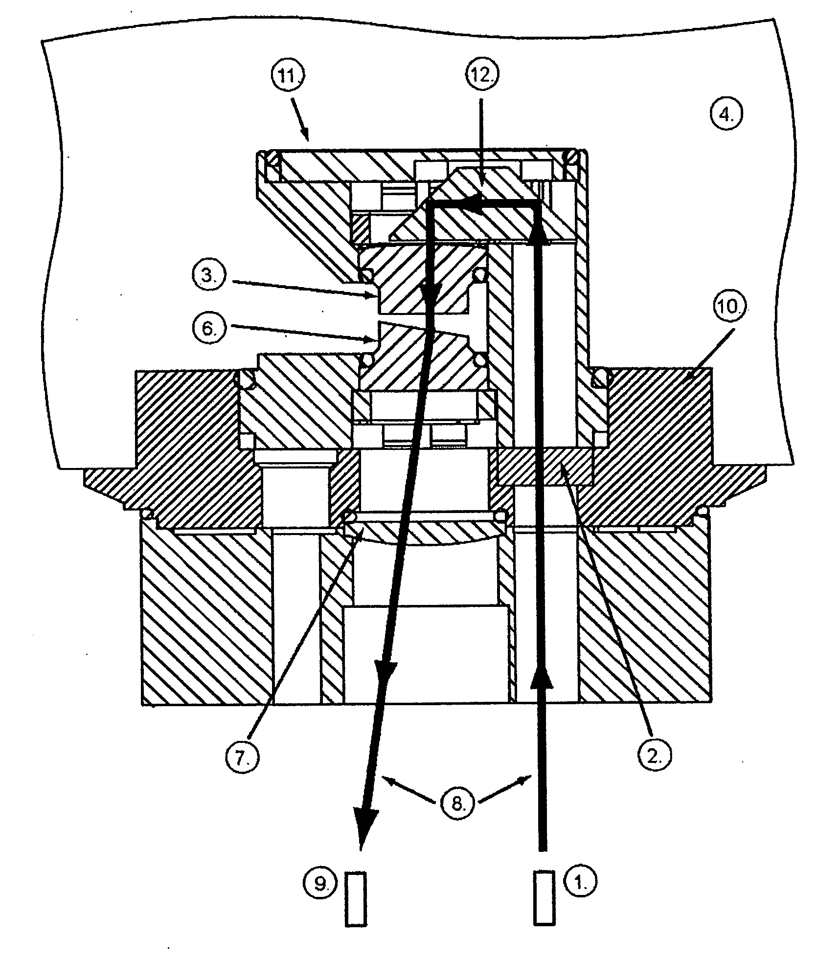
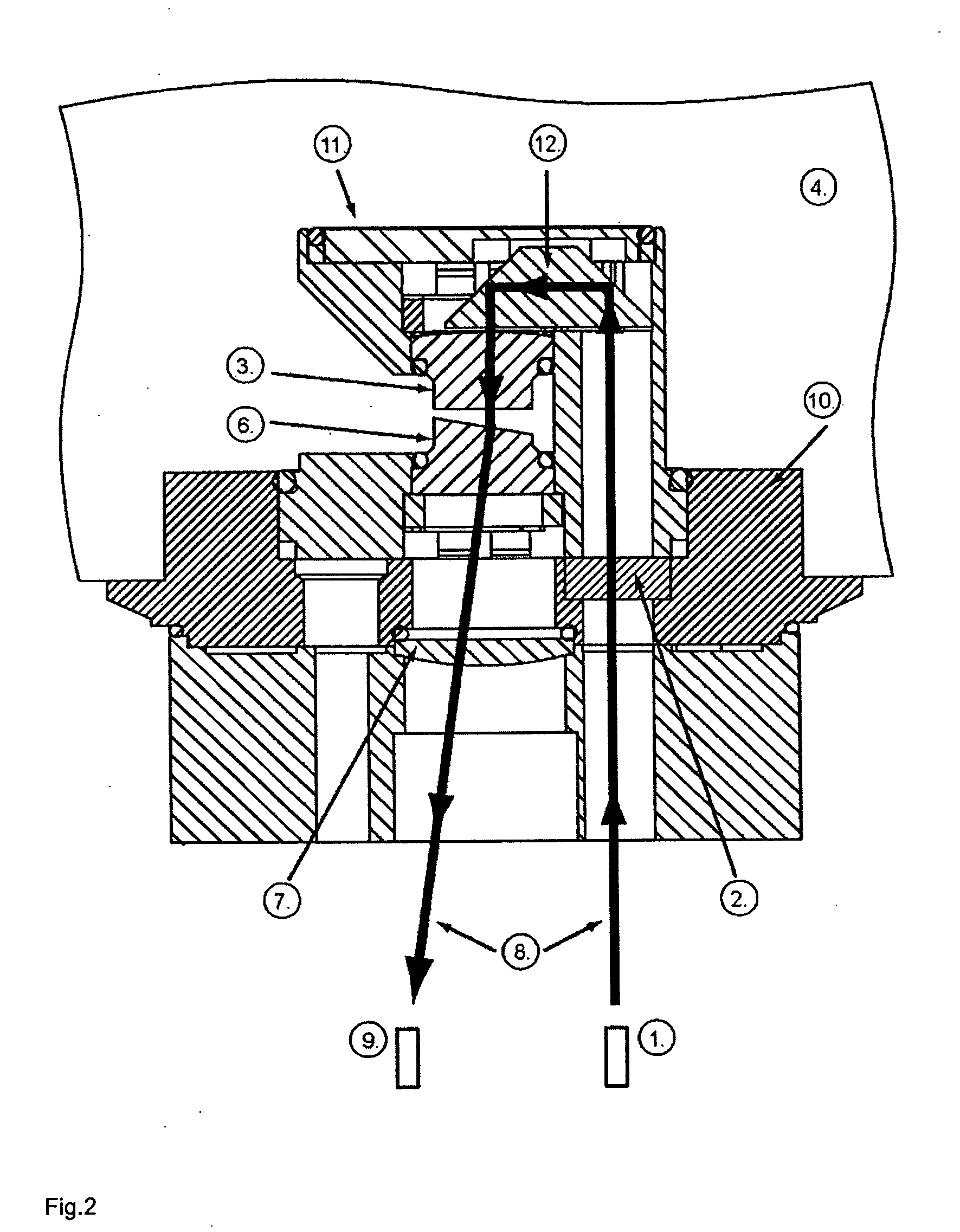
[0038]FIG. 2 is a diagram of the inventive transmitted light refractometer, with the beam path;

[0039]FIG. 3 is an optical diagram of a double prism;

[0040]FIG. 4 depicts the embodiment with a temperature sensor.

[0041]FIG. 1 is a diagram of a refractometer from the prior art that is based on the transmitted light principle. Light is emitted from a light source and illuminates a slit 1. The slit 1 is imaged by means of an illumination optics unit 2, preferably a lens. The illumination optics unit parallelizes the beam 8 before it passes through the process medium 4. The light enters the process medium 4 perpendicular thereto via a window 3. The light diffraction relevant to the refractive index measurement occurs at the interface between process medium and measurement prism 6. A sharp image of the slit is produced in the...


PUM


Abstract

A transmitted light refractometer allows high measurement accuracy across a broad measurement range, even under difficult measuring conditions. The transmitted light refractometer can be connected to a process simply via a single access. In accordance with advantageous features, the transmitted light refractometer covers a measurement range for all practically relevant media and includes integrated temperature compensation. A deflecting optics unit is arranged relative to an illumination optics unit such that the deflecting optics unit deflects a parallel beam through the process liquid and a measurement prism into the transmitted light refractometer back to the side from which it was radiated. The illumination optics unit, an imaging optics unit, and a detector plane are arranged on the light radiation side such that only one process access is needed.

Description

[0001]The invention relates to a transmitted light refractometer that works according to the principle of a transmitted light refractometer. A light source illuminates a slit. Using optical components, the emitted light is directed as a beam and enters the process medium through a window. The light passes through the process medium as a parallel beam. The light refraction that is relevant for the measurement occurs when the light re-enters the refractometer through the measurement prism. Optical components produce an image of the slit on the light-sensitive location detector. The light refraction of the process medium is determined from the position determined for the slit image.PRIOR ART[0002]The working principle for refractometers has been known for more than one hundred years. In addition to various laboratory tasks, refractometers are increasingly employed in industry. Refractometers are used in the chemical, pharmaceutical, and foods industries for process control and / or onlin...

Claims


Application Information

Patent Timeline
23 Apr 2009
Publication
US20090103076A1
IPC
G01N21/41
CPC
G01N21/4133; G01N2021/414; G01N21/43
Inventors
GLOECKNER, ANDREAS