Method and apparatus for finishing a workpiece

a technology for workpieces and finishing methods, applied in the direction of superfinishing machines, grinding machine components, manufacturing tools, etc., can solve the problems of reducing the overall effectiveness of abrasives, abrasives will fracture, and no longer remove a measurable amount of workpiece materials, so as to reduce the potential loss of processing tool efficiency and improve the rate of stock removal

Inactive Publication Date: 2009-04-23
THIELENHAUS MICROFINISH
View PDF15 Cites 12 Cited by
  • Summary
  • Abstract
  • Description
  • Claims
  • Application Information

AI Technical Summary

Benefits of technology

[0014]In one embodiment of the invention, the torque of various servomotors used in the material removal apparatus is monitored and compared to a known predetermined value. If the torque of the servomotors exceeds a predetermined level, the torque is reduced to a level at or below the predetermined level to reduce potential loss of pro

Problems solved by technology

This completes the geometry portion of the microfinishing process, as the abrasive no longer removes a measurable amount of the workpiece material.
One of the problems associated with a microfinishing process is maintaining the effectiveness of the abrasive such that it removes the initial roughness and reaches the solid, base material of the workpiece.
Depending upon the coarseness of the workpiece and the force applied on the abrasive, for example, abrasive particles located on a microfinishing film, the abrasive may fracture thus reducing the overall effectiveness of the abrasive, in this case the microfinishing film.
If the surface texture of

Method used


Image

  • Method and apparatus for finishing a workpiece
  • Method and apparatus for finishing a workpiece
  • Method and apparatus for finishing a workpiece

Examples


Embodiment Construction

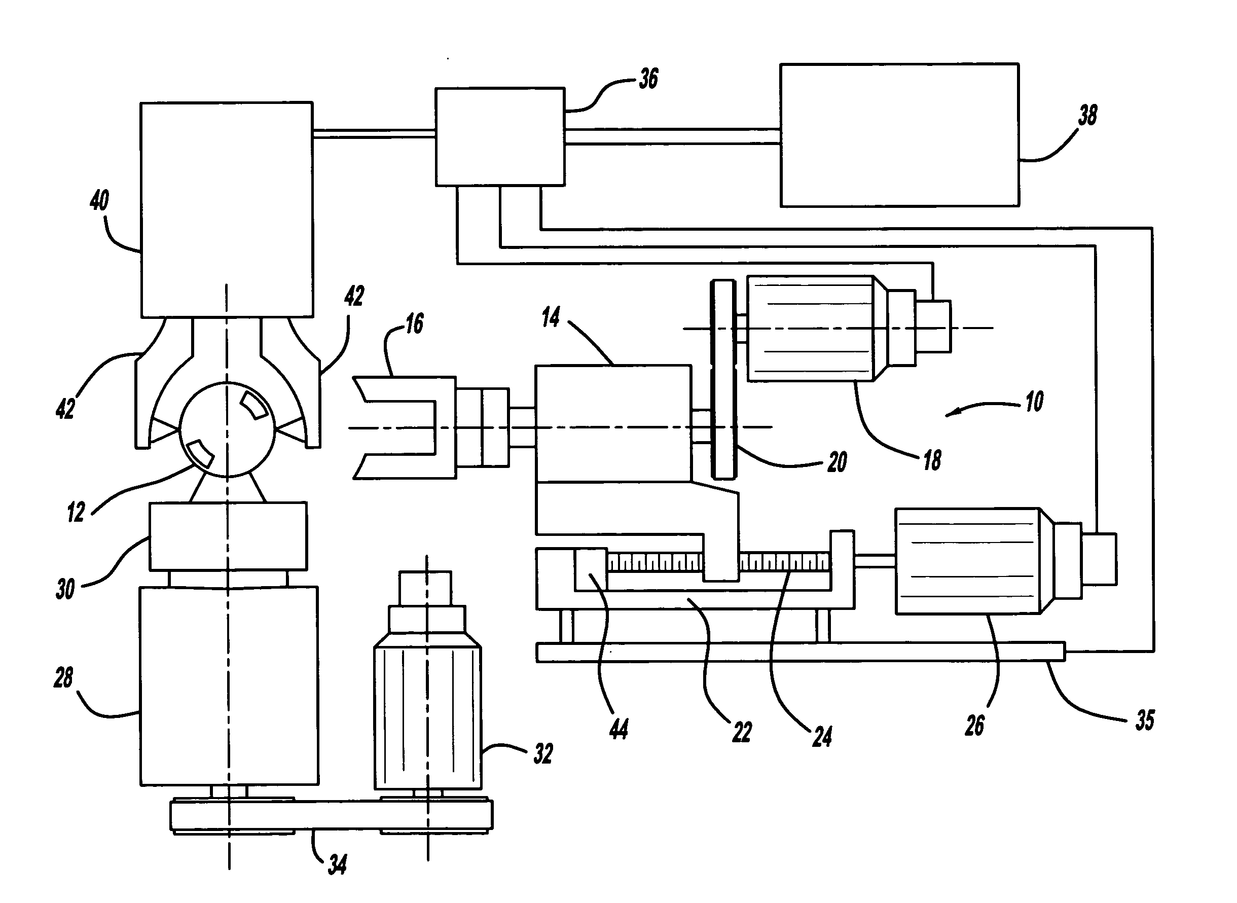
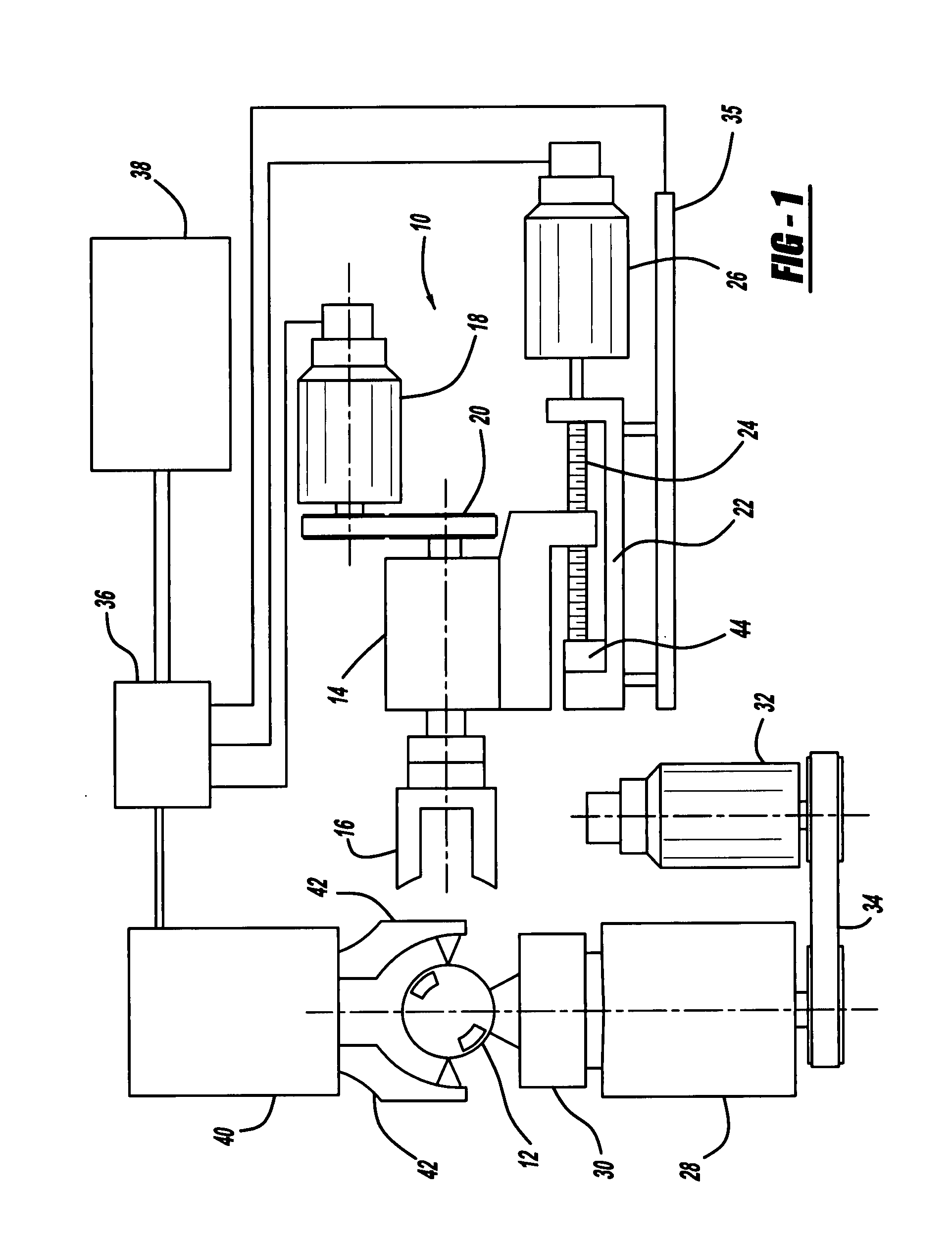
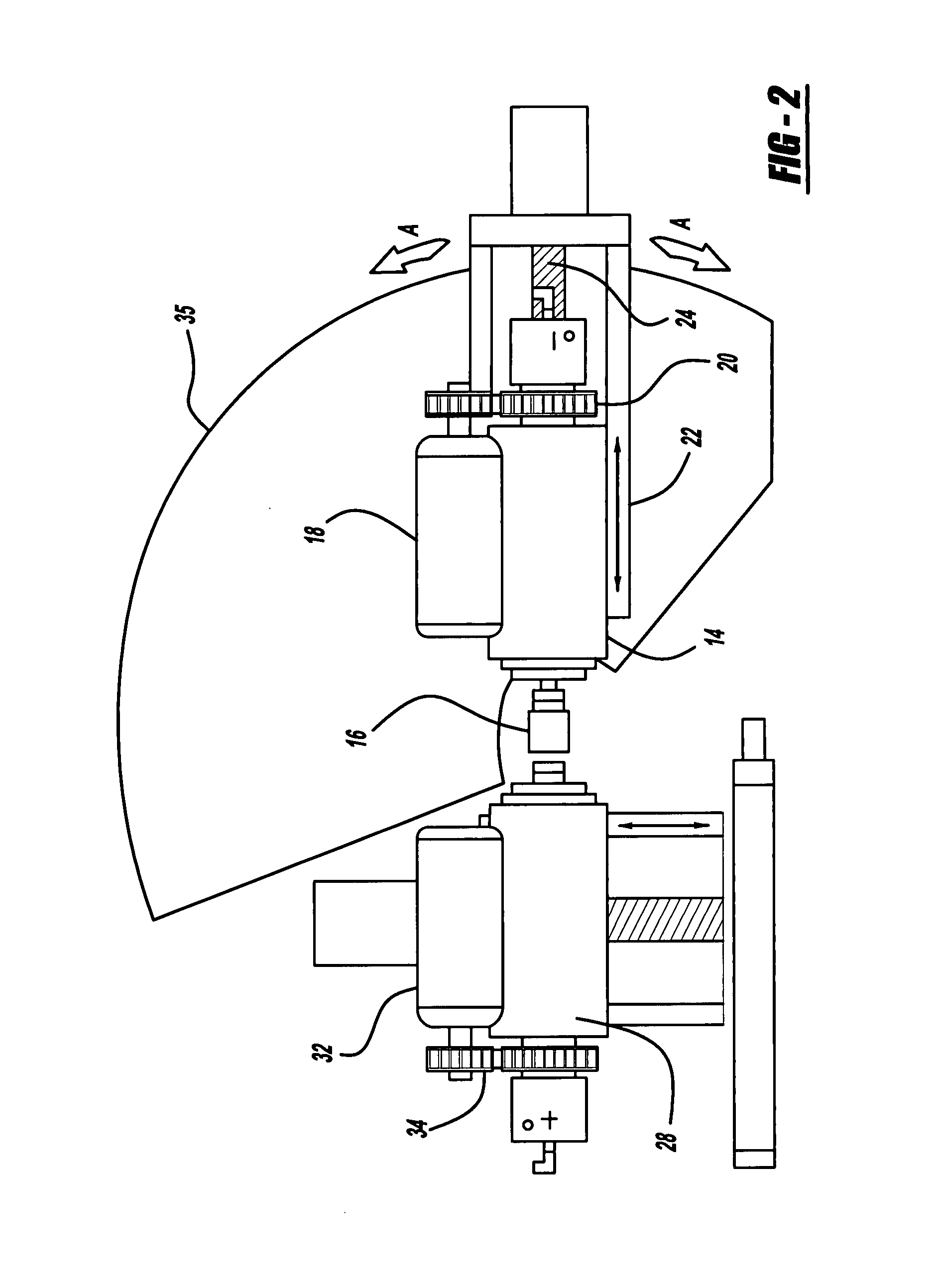
[0023]Turning now to FIG. 1, there is shown a microfinishing apparatus, seen generally at 10, for use in finishing a workpiece 12 which could be a ceramic, metal, carbon, graphite, or other material. The microfinishing apparatus 10 includes a tool spindle 14 supporting a processing tool 16 used to finish the workpiece 12. While shown herein as a finishing stone, the processing tool 16 may also include a tape or film having an abrasive material located thereon. A tool spindle servomotor 18 connects to and drives the tool spindle 14 through a pulley and timing belt arrangement 20. The tool spindle 14 is mounted for reciprocal movement on a tool slide 22. As illustrated herein, the tool spindle 14 is mounted on a non-preloaded ball screw 24. A tool slide servomotor 26 connected to the ball screw 24 operates to rotate the ball screw 24 and correspondingly move the tool spindle 14 and processing tool 16 into engagement with the workpiece 12. The tool slide 22 and related pulley and timin...


PUM

PropertyMeasurementUnit
Timeaaaaaaaaaa
Forceaaaaaaaaaa
Pressureaaaaaaaaaa

Abstract

A method for abrasive material removal that includes the steps of establishing an optimum force profile relating to the force or contact pressure applied by a processing tool on a workpiece. The actual force generated during the metal removal operation is monitored and compared to the optimum force profile. Based on the comparison of the actual force with the optimum force profile machine parameters are adjusted such that the actual force generated follows the established optimum force profile.

Description

CROSS-REFERENCE TO RELATED APPLICATIONS[0001]Not ApplicableFEDERALLY SPONSORED RESEARCH OR DEVELOPMENT[0002]Not ApplicableREFERENCE TO SEQUENCE LISTING[0003]Not ApplicableBACKGROUND OF THE INVENTION[0004]1. Field of the Invention[0005]The present invention relates generally to a method and apparatus for finishing a workpiece. More specifically, the method and apparatus measures or monitors various operating parameters occurring during the finishing operation of a workpiece and varies different operating parameters to maintain optimum predetermined or established values.[0006]2. Description of Related Art[0007]Microfinishing is a unique process that removes surface defects caused by previous operations to produce a high quality finish. The process involves utilizing an abrasive fed against the workpiece under a low or constant force. As is known, the abrasive determines the rate or duration of the feed. After the abrasive removes the initial roughness and reaches the solid, base mate...

Claims


Application Information

Patent Timeline
IPC IPC(8): B24B1/00
CPCB24B1/00B24B35/00B24B33/00
Inventor DINARDI, PETER C.
Owner THIELENHAUS MICROFINISH
Why Eureka
Try Eureka