
Wire cutting method

a wire cutting and wire technology, applied in the direction of electrolysis components, electric circuits, manufacturing tools, etc., can solve the problems of affecting the cutting effect of wire electrodes, so as to improve the cutting effect, and suppress the oscillation of wire electrodes

Active Publication Date: 2015-11-24
AGIE CHARMILLES
View PDF14 Cites 3 Cited by
  • Summary
  • Abstract
  • Description
  • Claims
  • Application Information

AI Technical Summary

Benefits of technology

The patent text describes methods for improving the efficiency of wire cutting in machining equipment. The technical effects are higher cutting rates and greater productivity of the machining equipment.

Problems solved by technology

The higher the workpiece is, the more difficult the flushing conditions become.
The contamination of the spark gap is comparatively low, although this is somewhat of a hindrance for a stable process.
However, when the workpiece height is relatively large, advance is only very slow.

Method used


Image

  • Wire cutting method
  • Wire cutting method
  • Wire cutting method

Examples


Embodiment Construction

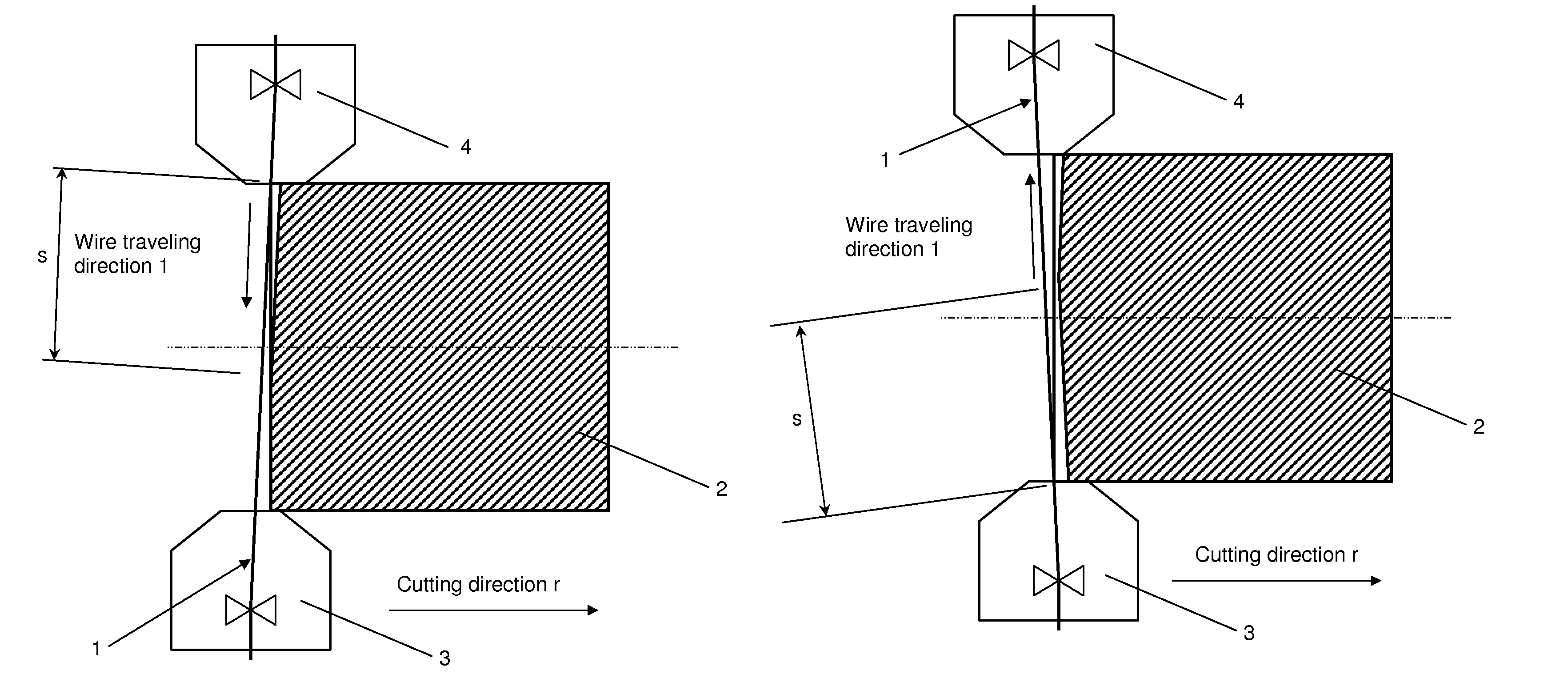
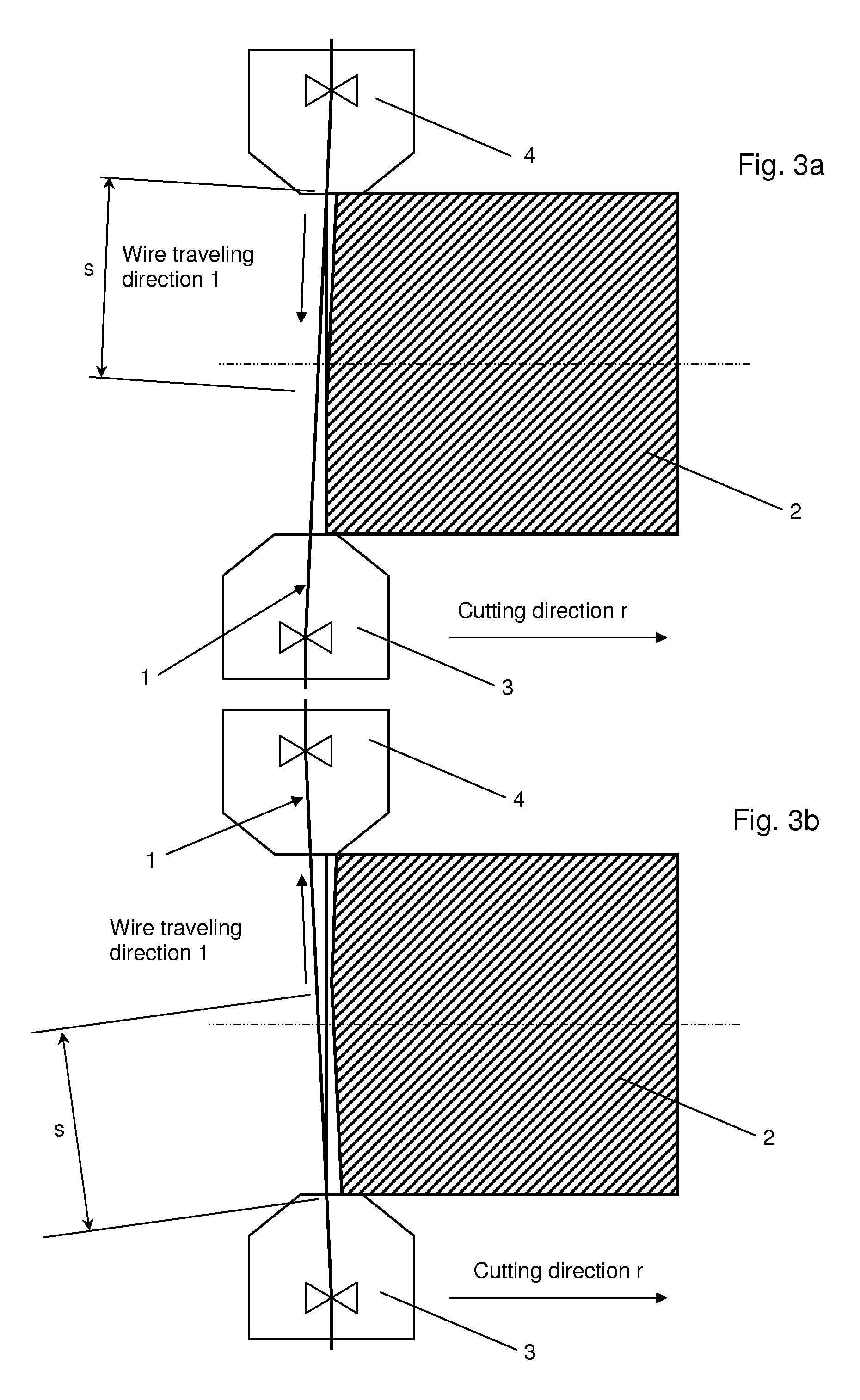
[0020]As mentioned above, the invention relates to a method for cutting by means of at least one traveling wire 1 which is inclined alternately in at least two different specific angular positions in the cutting direction r. The effective cutting height s is therefore smaller than the entire workpiece height h or smaller than the cutting height which is obtained during cutting with a single specific angular position of the wire (that is to say, without a periodic setting of a second angular position in the cutting direction).

[0021]A changeover is made, for example, periodically between a first and a second specific angular position, the wire 1 in each case being inclined in the cutting direction. Machining in the two specific angular positions of the wire 1 is preferably set for the same time duration. Thus, the traveling wire 1 is not in engagement over the entire workpiece height, but instead, on average, only over half the workpiece height. The evacuation of the removed particles...


PUM

PropertyMeasurementUnit
heightaaaaaaaaaa
heightaaaaaaaaaa
diameteraaaaaaaaaa

Abstract

A method for cutting by a traveling wire, wherein the wire traveling direction of the wire and / or the workpiece are / is inclined alternately in relation to one another into at least two different specific angular positions in the cutting direction, with the result that the effective cutting height (s) on the workpiece (2) becomes smaller than the entire workpiece height.

Description

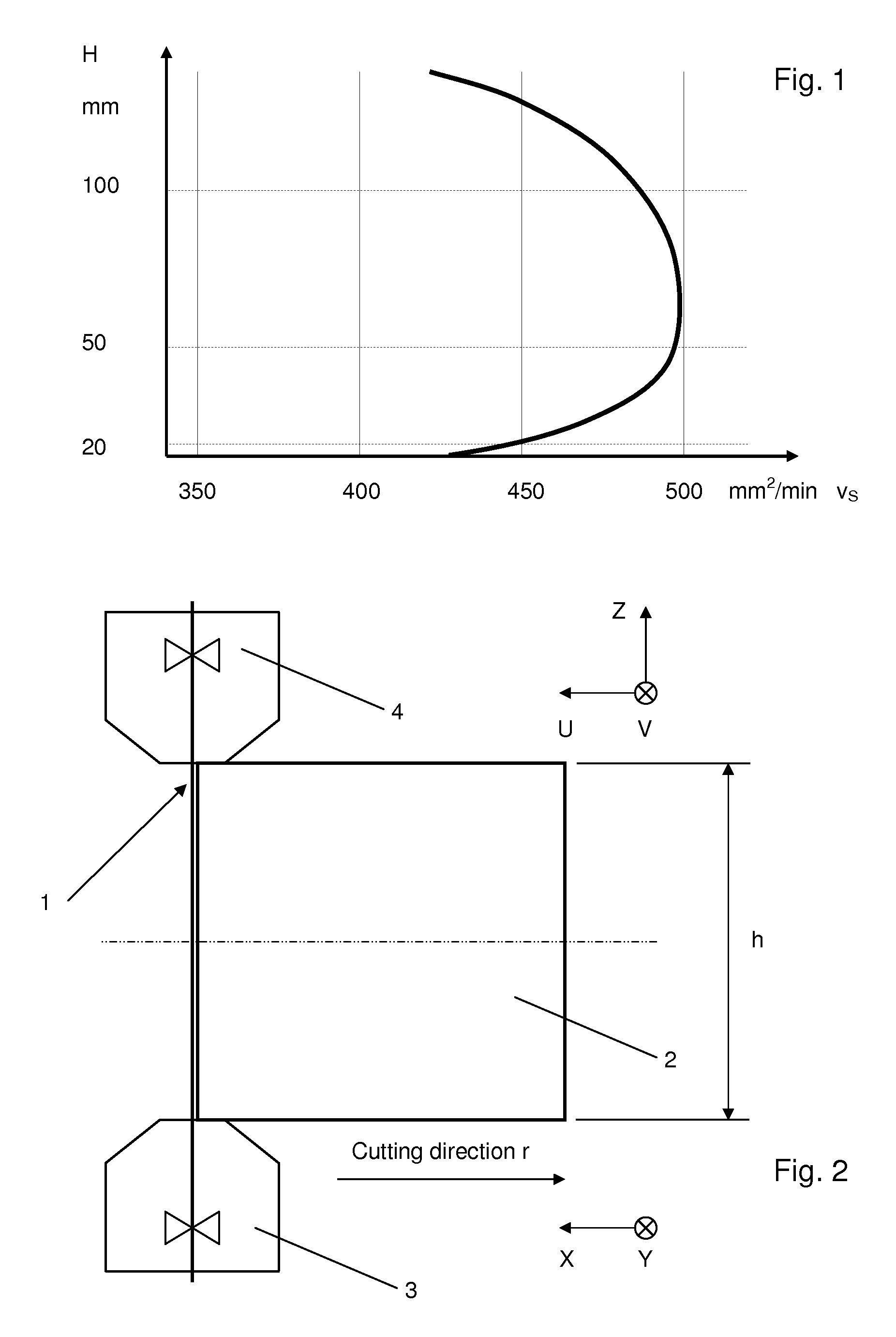
BACKGROUND OF THE INVENTION[0001]The present invention relates to a method for cutting by means of a traveling wire.[0002]Wire electric discharge machines serve for the manufacture of blanking dies, punches, electrodes and extruding dies, but also for the manufacture of small to medium series and often in prototype construction.[0003]Under optimal conditions, modern wire electric discharge machines (WEDM) attain cutting rates of 500 mm2 / min in cold work steel. The cutting rate is dependent, inter alia, upon the workpiece height. Reference is made in this regard to the company publication “Experience” No. 23, Id. 027.158, of the company Agie SA, published in October 2003. A qualitative illustration of the cutting rate against the workpiece height will be gathered from the last page (back sheet) of this publication. This somewhat simplified graph starts with the workpiece height of 20 mm, but suggests that the cutting rate fall steeply with a low workpiece height. The illustration of ...

Claims


Application Information

Patent Timeline
Patent Type & Authority Patents(United States)
IPC IPC(8): B23Q5/22B26D1/547B24B1/00B23H1/02B23H7/06B26D1/553C25F7/00
CPCB23Q5/22B23H1/02B23H7/065B24B1/00B26D1/547B26D1/553C25F7/00Y10T83/05B23H7/02
Inventor BAUMELER, MARCO
Owner AGIE CHARMILLES
Learn More