Optical system for barcode scanner

an optical system and barcode scanner technology, applied in the field of barcode scanners, can solve the problems of not being able requiring an extra space in the z-axis, and unable to minimize the installation space, so as to avoid image noise, enhance the uniformity of light emitted, and less installation space

Inactive Publication Date: 2009-04-30
DOE JOHN +13
View PDF70 Cites 5 Cited by
  • Summary
  • Abstract
  • Description
  • Claims
  • Application Information

AI Technical Summary

Benefits of technology

[0007]The present invention has been accomplished under the circumstances in view. It is one object of the present invention to provide an optical system for barcode scanner, which requires less installation space. It is another object of the present invention to provide an optical system for barcode scanner, which enhances uniformity of the light emitted by the light source, avoiding image noise and improving barcode reading reliability.
[0008]To achieve these and other objects of the present invention, an optical system for barcode scanner comprises a standing cylinder lens, a light source that emits a light beam through the standing cylinder lens onto the barcode of the product to be scanned, a focusing lens that focuses the image reflected by the barcode, a linear sensor array, and a slanted arranged reflector that reflects the image focused by the focusing lens onto the linear sensor array for reading. The light path of the image focused by the focusing lens onto the reflector and the light path of the image reflected by the reflector onto the linear sensor array are overlapped, forming a light path overlap region. By means of the characteristic of the light path overlap region, the optical system requires less installation space, and therefore the dimension of the barcode scanner can be greatly reduced.
[0009]Further, slight oscillation means is provided to cause slight oscillation of the emitted light beam in direction perpendicular to the light path of the light source, enhancing uniformity of the light, and therefore the reading reliability of the barcode scanner is greatly improved.

Problems solved by technology

In consequence, the dimension of the barcode scanner cannot be minimized.
However, because the light path of the image reflected by the reflector is an independent light path, it requires an extra space in z-axis.
Therefore, this design cannot minimize the installation space.
However, this preservation space B1 is too small for direct use.
Therefore, an extra space at one lateral side relative to the optical system is usually used for the installation of the illumination light source, increasing the dimension and manufacturing cost of the barcode scanner.

Method used


Image

  • Optical system for barcode scanner
  • Optical system for barcode scanner
  • Optical system for barcode scanner

Examples


Embodiment Construction

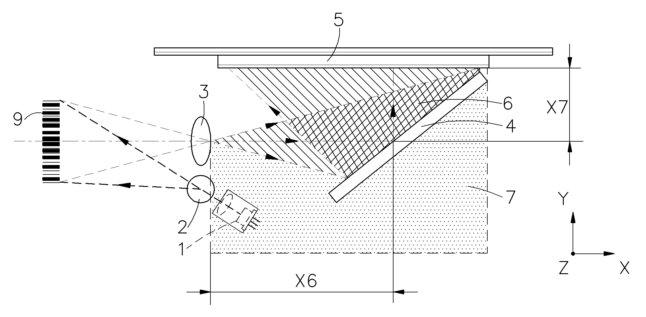
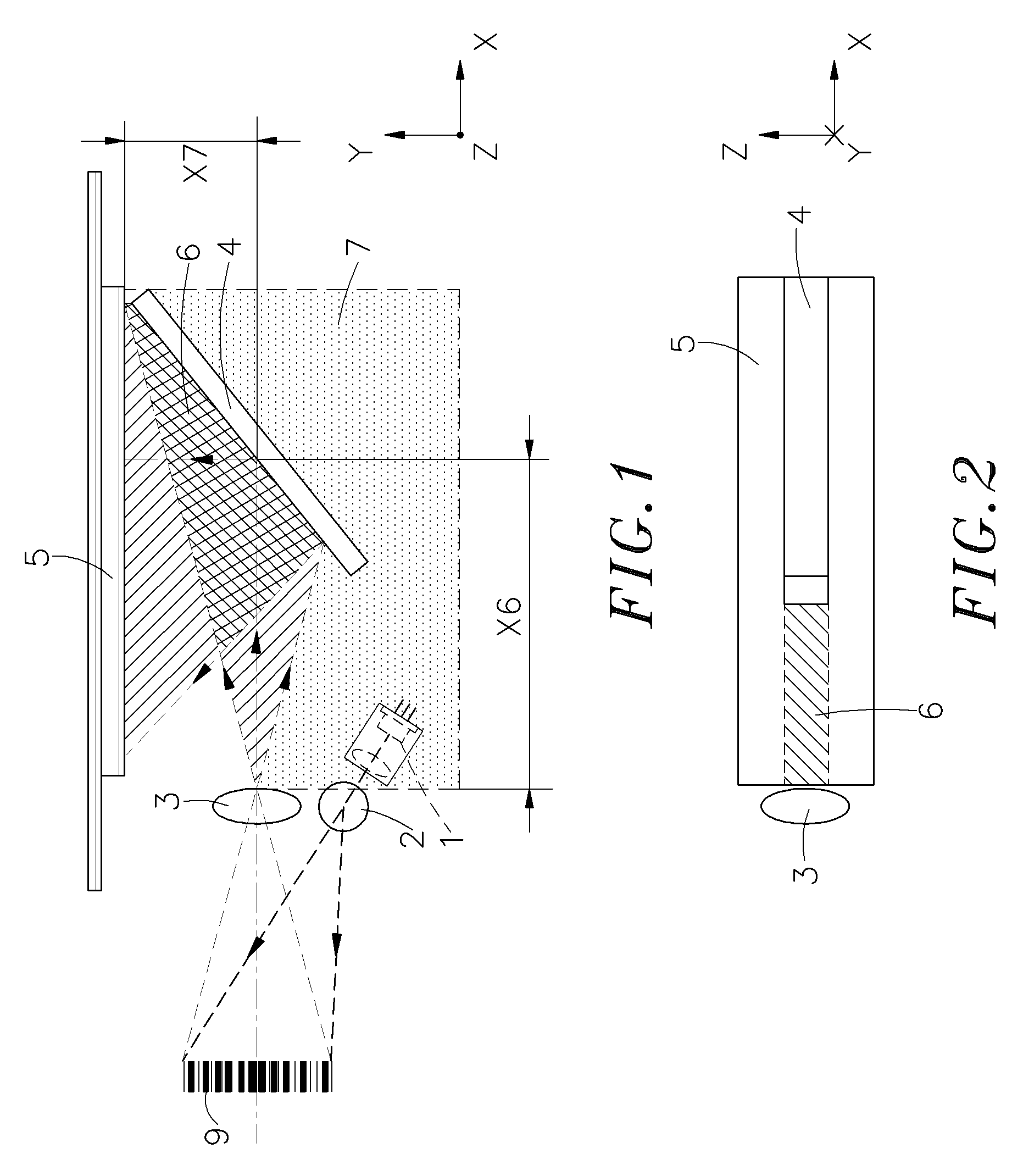
[0017]Referring to FIGS. 1 and 2, an optical system for barcode scanner in accordance with a first embodiment of the present invention is shown comprising a light source 1, a standing cylinder lens 2, a focusing lens 3, a reflector 4, and a linear sensor array 5.

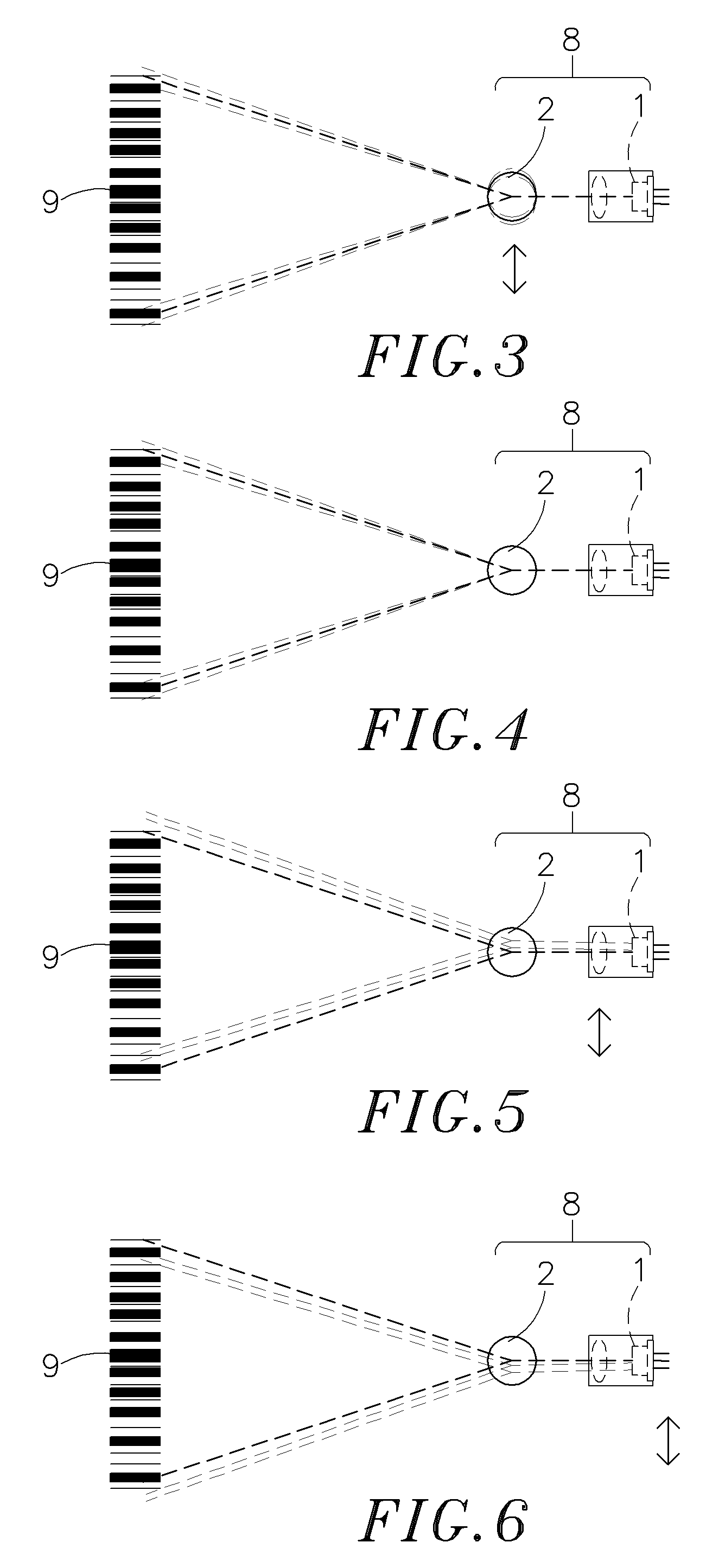
[0018]The light source 1 is formed of a light emitting device and a collimator. Further, the light beam produced by the light source 1 falls upon the plane of the product's barcode 9 to be scanned at a slanting angle.

[0019]The standing cylinder lens 2 is adapted to expand the light beam produced by the light source 1 into a line-shaped light beam to fall upon the barcode 9 of the product to be scanned.

[0020]The focusing lens 3 is adapted to receive the barcode image reflected by the barcode 9 and to focus the barcode image. Further, the focal distance of the focusing lens 3 is X.

[0021]The reflector 4 is adapted to reflect the image focused by the focusing lens 3.

[0022]The linear sensor array 5 is adapted to receive the image...


PUM

PropertyMeasurementUnit
crystal structureaaaaaaaaaa
focal distanceaaaaaaaaaa
lengthaaaaaaaaaa

Abstract

An optical system used in a barcode scanner is disclosed to include a standing cylinder lens, a light source that emits a light beam through the standing cylinder lens onto the barcode of the product to be scanned, a focusing lens that focuses the image reflected by the barcode, a linear sensor array, and a slanted arranged reflector that reflects the image focused by the focusing lens onto the linear sensor array for reading. The light path of the image focused by the focusing lens onto the reflector and the light path of the image reflected by the reflector onto the linear sensor array are overlapped, forming a light path overlap region.

Description

[0001]This application is a Continuation-In-Part of my patent application, Ser. No. 11 / 423,955, filed on Jun. 14, 2006.BACKGROUND OF THE INVENTION[0002]1. Field of the Invention[0003]The present invention relates to a barcode scanner and more particularly, to an optical system for barcode scanner, which has the component parts thereof arranged on one same plane in such a manner that the light path of the image focused by the focusing lens onto the reflector and the light path of the image reflected by the reflector onto the linear sensor array are overlapped, enabling the dimension of the barcode scanner to be minimized.[0004]2. Description of the Related Art[0005]Conventional barcode scanners commonly use a linear sensor array to receive reflective image from the barcode. The light beam on the barcode for the reflective image received by the linear sensor array is preferably in a uniform status to facilitate further barcode signal processing. In a conventional barcode scanner, the ...

Claims


Application Information

Patent Timeline
Patent Type & Authority Applications(United States)
IPC IPC(8): G06K7/10
CPCG06K7/10702G06K7/10732G06K7/10831H02K1/14A01B1/00A61K48/00C07D487/04
Inventor TIEN, KAI-YUAN
Owner DOE JOHN
Why Eureka
Try Eureka