Method and device for the non-contact measurement of a displacement of components relative to one another

Inactive Publication Date: 2009-04-30
ZF FRIEDRICHSHAFEN AG
View PDF5 Cites 3 Cited by
  • Summary
  • Abstract
  • Description
  • Claims
  • Application Information

AI Technical Summary

Benefits of technology

[0021]A design feature of the field barrier elements provides that in the longitudinal direction, the bars, cables, strips or suchlike have serrations along the edge with regularly spaced teeth and gaps, such that by virtue of the relative displacement of the components, these bars, cables, strips or suchlike can move

Problems solved by technology

They are less suitable for determining a relative displacement (path difference) of a first component, relative to a second component which, for their part, undergo an absolute movement relative to a fixed structure.
However, both methods or arrangements suffer from disadvantages, as explained below.
The disadvantage, however, is that the sensor signals fro

Method used


Image

  • Method and device for the non-contact measurement of a displacement of components relative to one another
  • Method and device for the non-contact measurement of a displacement of components relative to one another
  • Method and device for the non-contact measurement of a displacement of components relative to one another

Examples


Embodiment Construction

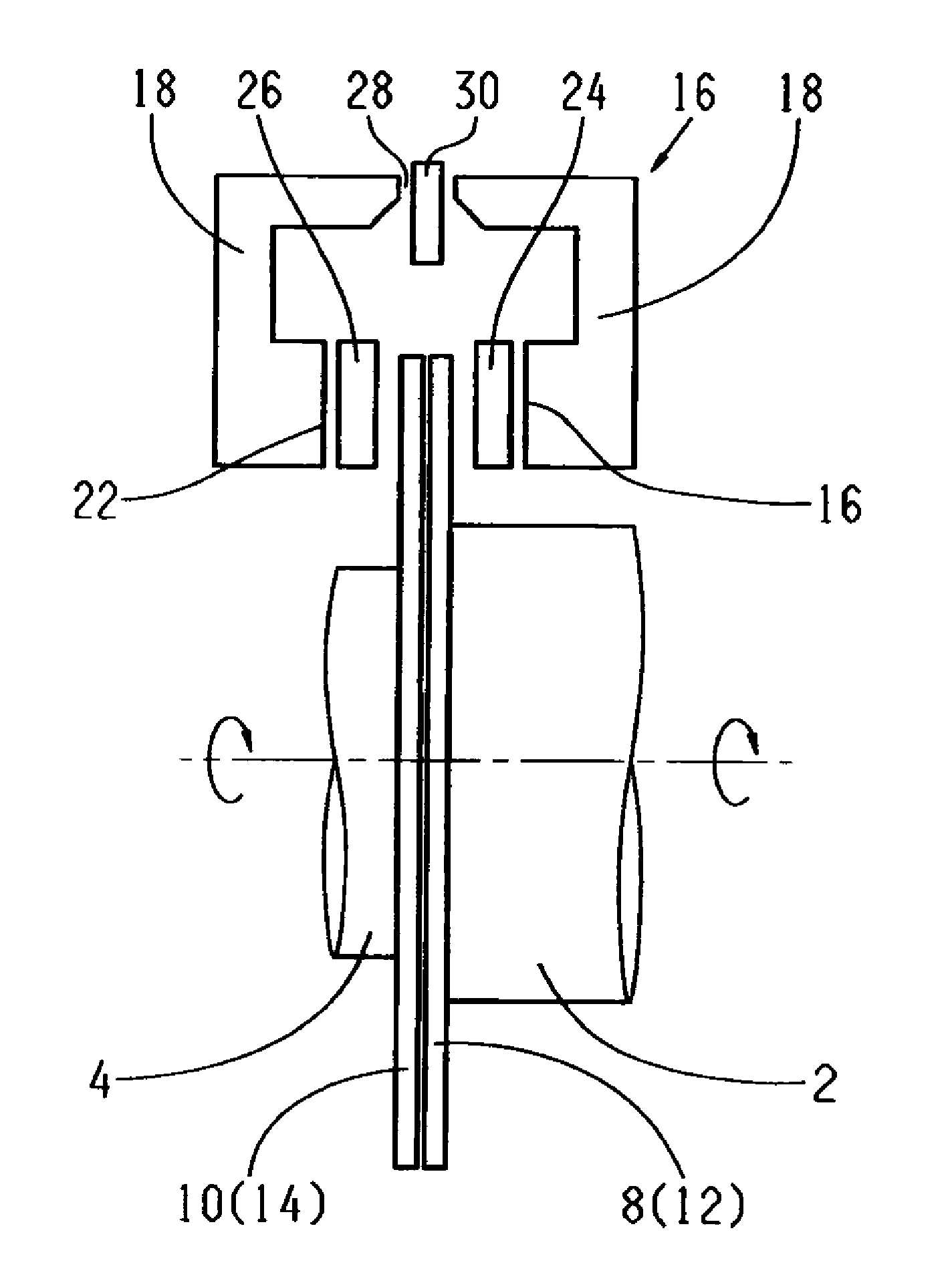
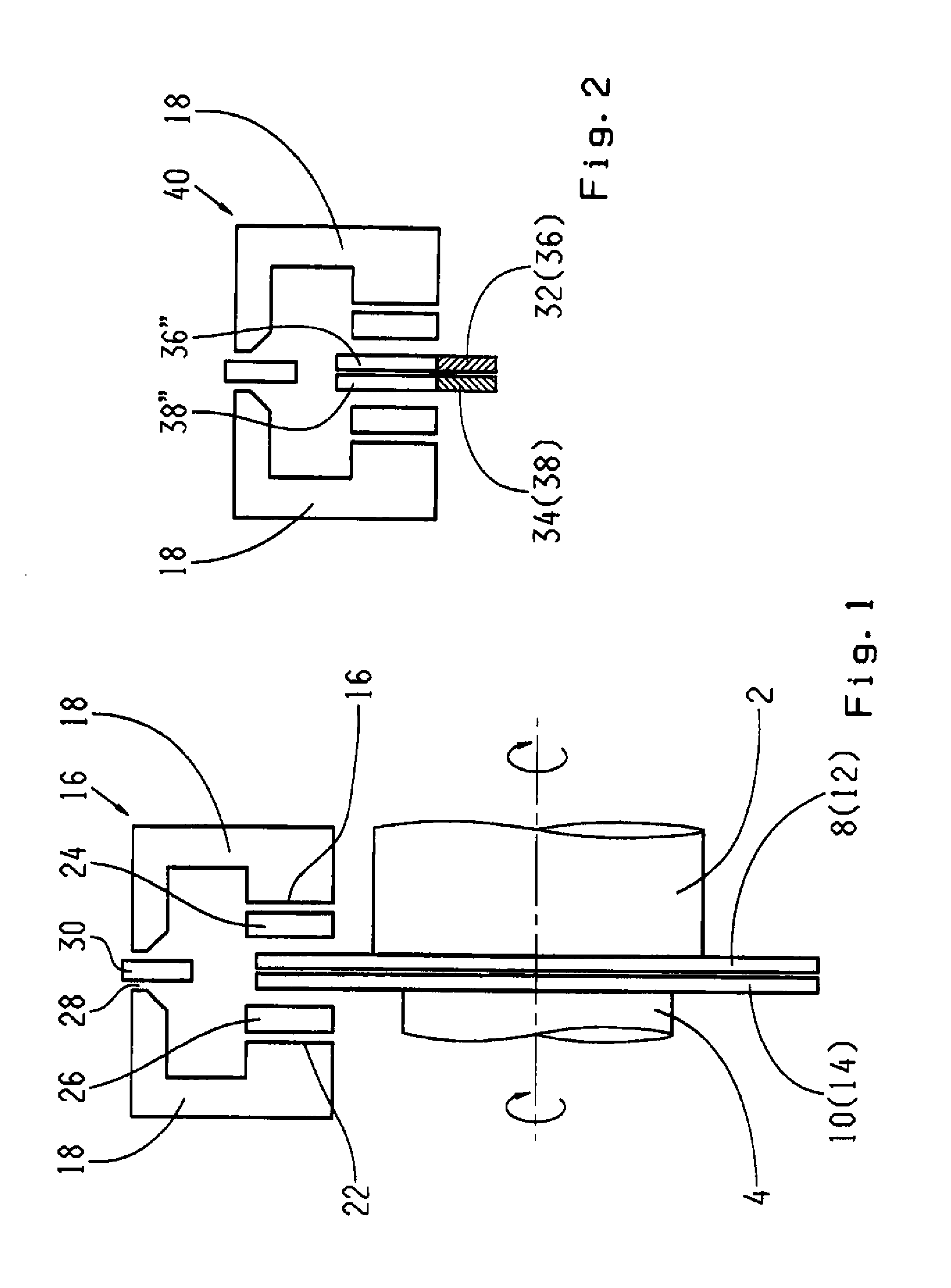
[0030]FIG. 1 shows a first shaft 2 and a second shaft 4, both mounted to rotate about a common rotation axis 6 in a positionally fixed structure (not shown) and which, during operation, both rotate in the same direction but at different speeds. To determine a relative rotation of the two shafts 2 and 4 with respect to one another, at the ends of these shafts, facing one another, are arranged disks 12 and 14 that function as field barrier elements 8 and 10, respectively, whose rotation, relative to one another, can be determined in a manner described below and evaluated in an evaluation unit (not shown).

[0031]Associated with the field barrier elements 8, 10 is a magnetic circuit arrangement 16, which produces a magnetic field that permeates the radially outer edge of the disks 12, 14. The magnetic field arrangement 16 comprises a magnetic bridge 18 which encompasses the edge of the field barrier elements like a stirrup, which is made from a ferromagnetic material and at whose ends 20...


PUM


Abstract

A method and device for non-contact measurement of relative displacement (path difference) between a first component (2) and a second component (4), which are moving in an absolute sense to a structure that is fixed in position. The device includes a field barrier element (8, 10) arranged on each of the two components. These elements have structures that result in different magnetic permeation resistances at different relative overlaps. The field barrier elements project into a magnetic field that permeates them. A means (30) is associated with this magnetic field for determining the magnetic field strength that varies as a function of overlap of the field barrier elements and for evaluating the values determined.

Description

[0001]This application claims priority from German Application Serial No. 10 2007 000 597.2 filed Oct. 30, 2007.FIELD OF THE INVENTION[0002]The invention concerns a method for measuring displacement of components relative to one another without contact and a device for implementing the method.BACKGROUND OF THE INVENTION[0003]Non-contact measurement methods and measurement devices are basically known. The sensors, used in such cases, generally work on the basis of magnetic or inductive functional principles, i.e., they measure the change of magnetic field strength or inductivity, brought about by the movement of a component relative to the positionally fixed sensor. The movement of the magnet detected by the sensor is evaluated in an evaluating unit and converted to a movement signal or movement display.[0004]Such measurement methods and devices are entirely suitable for the determination of absolute displacements or rotations relative to a fixed structure. They are less suitable for...

Claims


Application Information

Patent Timeline
IPC IPC(8): G01B7/14
CPCG01B7/003G01D5/147G01B7/30G01B7/14G01D2205/40
Inventor KURTH, JORG
Owner ZF FRIEDRICHSHAFEN AG
Why Eureka
Try Eureka