Liquid droplet jetting head

Active Publication Date: 2009-04-30
BROTHER KOGYO KK
View PDF2 Cites 9 Cited by
  • Summary
  • Abstract
  • Description
  • Claims
  • Application Information

AI Technical Summary

Benefits of technology

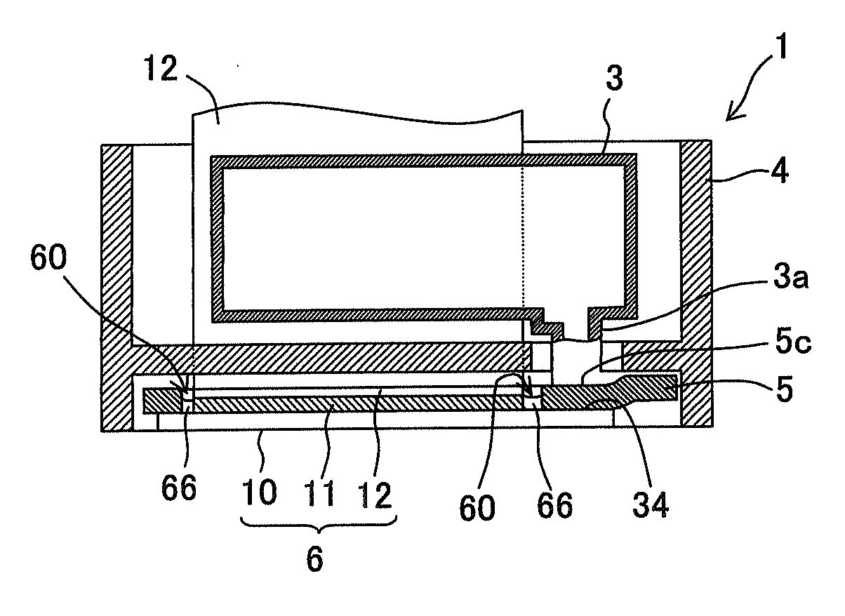
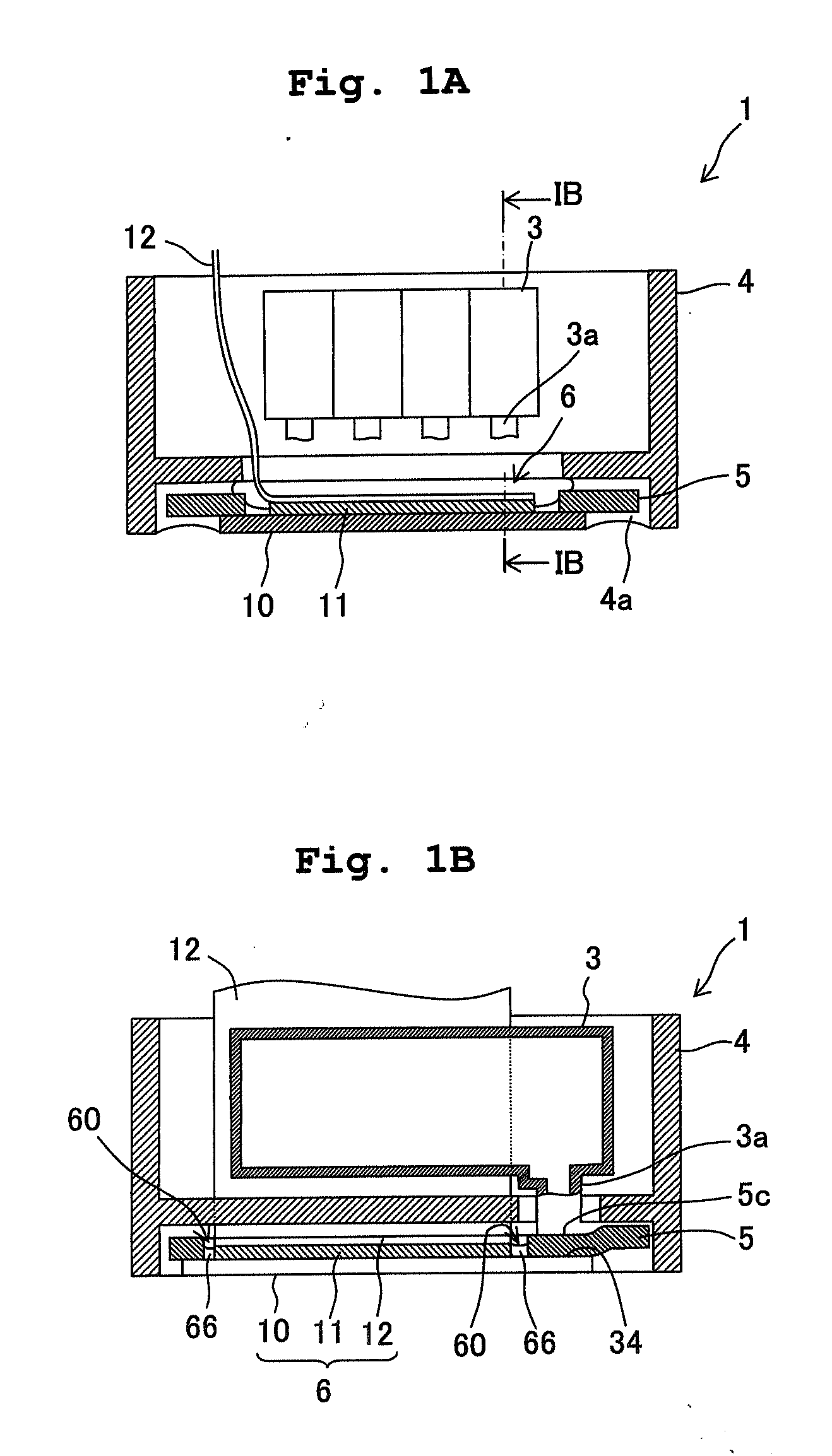
[0011]An object of the present invention is to provide a liquid jetting head which is capable of carrying out easily a job of applying the sealing agent, and sealing appropriately the opening portion of the gap between the piezoelectric unit and the wiring unit.
[0040]Moreover, since the introducing groove is formed in the trapping groove, it is also possible to carry out easily and assuredly a job of applying the sealing agent, and to prevent the electrical shorting due to an ink leakage, by sealing appropriately the gap between the surfaces facing of the piezoelectric unit and the wiring unit.

Problems solved by technology

Incidentally, in the liquid droplet jetting head as disclosed in Japanese Patent Application Laid-open No. 2006-44196, there is a fear that the ink leaks from a connecting portion between the ink outflow port and the ink inflow port.
Moreover, there is a fear that the ink is leaked from the nozzle holes, when a user drops the ink-jet printer apparatus.
In such a case, there is a fear that the leaked ink enters a small gap between the piezoelectric unit and the wiring unit.
In this case, it is not preferable because the leaked liquid may cause a shorting (short-circuit) between the unexpected electrode terminals.
However, a structure which is appropriate for preventing the liquid entering from an outside has not been disclosed.
For instance, when the electroconductive adhesive is once filled in the lateral groove during the connection between the terminals, it becomes impossible to prevent the liquid from entering from outside later.
However, due to a warp (curling) of the wiring unit and an unevenness of the piezoelectric unit surface, the opening portion of the gap at the time of connecting often becomes uneven.
Therefore, the entire opening portion might not be sealed appropriately.
Moreover, in order to deal with this, after carrying out the first application and drying of the liquid-type sealing agent, a visual check is carried out, and it is necessary to carry out the second application on a portion, which is not sealed appropriately.
However, such a job is too complicated, and sealing appropriately by applying and drying once has been sought.

Method used


Image

  • Liquid droplet jetting head
  • Liquid droplet jetting head
  • Liquid droplet jetting head

Examples


first embodiment

[0075]FIG. 4 is a plan view showing the structure (arrangement) for preventing an entry of a liquid into the gap between the connecting surfaces of the piezoelectric unit 11 and the wiring unit 12. FIG. 4 shows a structure of the wiring unit 12 from a rear surface side (side of a surface facing the piezoelectric unit 11). FIG. 5 is a cross-sectional view taken along a line V-V in FIG. 4, showing the wiring unit 12 in FIG. 4 stacked on the piezoelectric unit 11.

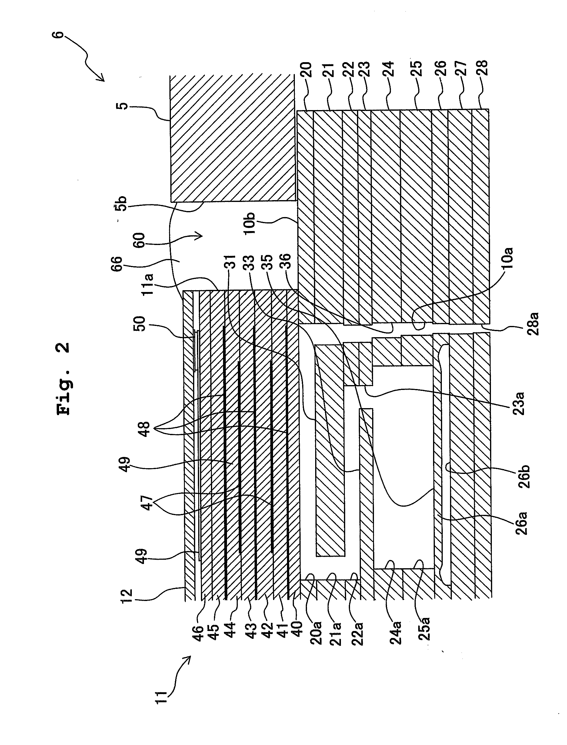
[0076]As shown in FIG. 3, the plurality of drive electrodes 49 including a plurality of individual drive electrodes 49a and a common drive electrode 49b are formed on the upper surface of the piezoelectric unit 11 (upper surface of the top sheet 46 shown in FIG. 2). The individual drive electrodes 49a are arranged in five rows in Y direction corresponding to the pressure chamber rows, and each row of individual drive electrodes 49a is extended in X direction. The common drive electrode 49b is arranged to be extended in the for...

second embodiment

[0085]FIG. 6 is a plan view showing another structure (arrangement) for preventing the entry of a liquid into the gap between the piezoelectric unit 11 and the wiring unit 12, and shows the structure of the wiring unit 12 from the rear surface side (side of a surface facing the piezoelectric unit 11). FIG. 7 is a partial cross-sectional view in which the wiring unit 12 shown in FIG. 6 is stacked on the piezoelectric unit 11.

[0086]The wiring unit 12 according to the second embodiment differs from the wiring unit 12 according to the first embodiment at the following two points. The first point is that, the covering layer 70 which covers the lower surface of the sheet-shaped substrate 12a has a two-layered structure of a first covering layer 75 and a second covering layer 76. The second point is that, the sealing agent infusing groove 73 is formed to be extended over the entire periphery surrounding the individual supply-terminal 50a and the common supply-terminal 50b. Consequently, th...

third embodiment

[0089]FIG. 8 is a plan view showing another structure for preventing the entry of a liquid into the gap between the piezoelectric unit 11 and the wiring unit 12, and shows the structure of the wiring unit 12 viewing from the rear surface side (side of the surface facing the piezoelectric unit 11). FIG. 9 is a partial cross-sectional view of the wiring unit 12 shown in FIG. 8 stacked on the piezoelectric unit 11. The wiring unit 12 according to the third embodiment has a structure in which the structure according to the first embodiment and the structure according to the second embodiment are combined.

[0090]In other words, as shown in FIGS. 8 and 9, the wiring unit 12 includes the covering layer 70 having a two-layered structure including the first covering layer 75 and the second covering layer 76. The cutout 77 which is extended over the entire periphery surrounding the individual supply-terminals 50a and the common supply-terminal 50b similarly as in the second embodiment is forme...


PUM


Abstract

An ink-jet head includes a channel unit in which a channel is formed, a piezoelectric unit, and a wiring unit stacked on the piezoelectric unit. The wiring unit has a substrate, an individual supply-terminal group which includes a plurality of individual supply-terminals, a common supply-terminal, and an isolative covering layer, which is stacked on a surface of the substrate facing the piezoelectric unit. In the covering layer, a trap groove which runs between the individual supply-terminals and the common supply-terminal, and surrounds the individual supply-terminal group is formed. Accordingly, there is provided a liquid droplet jetting head which is capable of preventing a shorting between the individual drive electrodes of the piezoelectric unit, and between the individual supply-terminals of the wiring unit, due to the liquid entered from outside.

Description

CROSS REFERENCE TO RELATED APPLICATION[0001]The present application claims priority from Japanese Patent Applications No. 2007-283399, filed on Oct. 31, 2007 and No. 2007-283397, filed on Oct. 31, 2007, the disclosures of which are incorporated herein by reference in its entirety.BACKGROUND OF THE INVENTION[0002]1. Field of the Invention[0003]The present invention relates to a liquid droplet jetting head which jets liquid droplets.[0004]2. Description of the Related Art[0005]As a liquid jetting apparatus such as an ink-jet printer, there is a liquid jetting apparatus which includes: a channel unit in which liquid channels communicating with nozzle holes for jetting liquid droplets; a piezoelectric unit which applies a jetting pressure to the liquid in the liquid channel to jet the liquid from the nozzle holes; and a liquid droplet jetting head on which a wiring unit for outputting a drive signal for the piezoelectric unit is stacked (for example, refer to Japanese Patent Application...

Claims


Application Information

Patent Timeline
IPC IPC(8): B41J2/045
CPCB41J2/14209B41J2002/14217B41J2002/14225B41J2002/14491B41J2002/14419B41J2002/14459B41J2002/14306
Inventor KUBO, TOMOYUKI
Owner BROTHER KOGYO KK
Why Eureka
Try Eureka