Optical Sensor and Operating Method Thereof

a sensor and optical mouse technology, applied in the field of sensors, can solve the problems of reducing unable to allow the sensor and dsp to function properly, and the surface does not allow the sensor and dsp to function properly, and achieve the effect of not affecting the efficiency of optical mous

Active Publication Date: 2009-04-30
PIXART IMAGING INC
View PDF8 Cites 8 Cited by
  • Summary
  • Abstract
  • Description
  • Claims
  • Application Information

AI Technical Summary

Benefits of technology

[0010]Accordingly, it is not necessary to adjust the frame rate of the optical sensor to compe

Problems solved by technology

However, some surfaces do not allow the sensor and DSP to function properly because the intensity of the reflecte

Method used


Image

  • Optical Sensor and Operating Method Thereof
  • Optical Sensor and Operating Method Thereof
  • Optical Sensor and Operating Method Thereof

Examples


Embodiment Construction

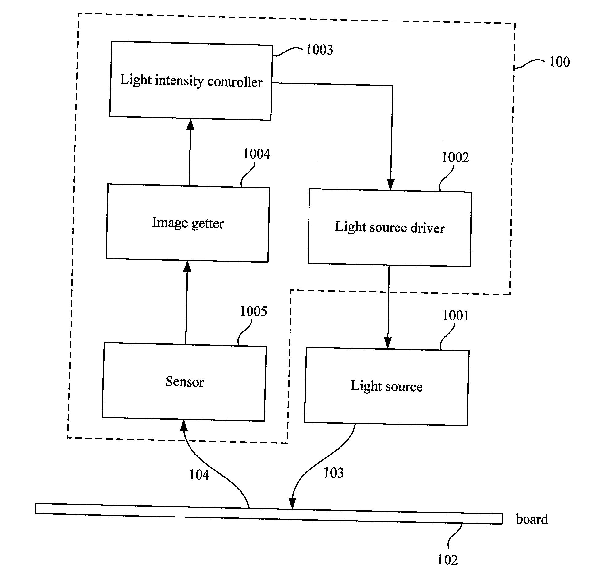
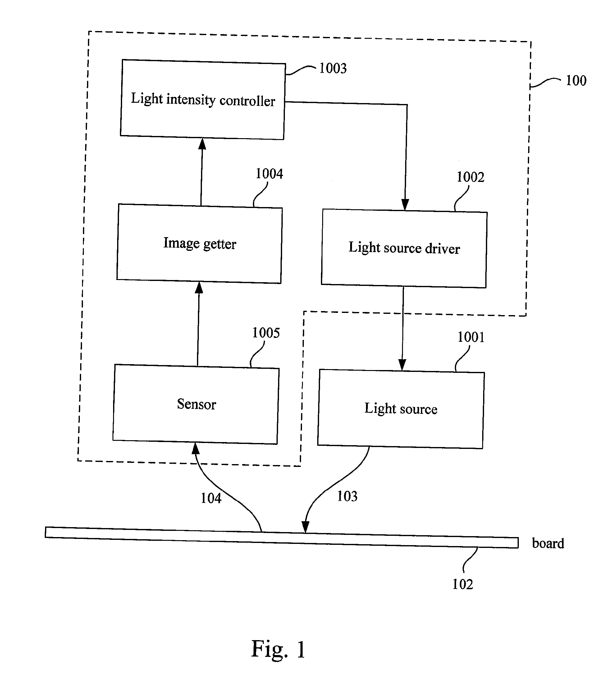
[0016]FIG. 1 illustrates a schematic diagram of an optical sensor that can adjust the light source intensity based on the surface condition according to an embodiment of the present invention. The optical sensor 100 comprises a light source 1001, a light source driver 1002, a light intensity controller 1003, an image capture device 1004 and a sensor 1005. In an embodiment, laser diodes or light emitting diodes can serve as the light source 1001.

[0017]In an embodiment, the optical sensor is disposed in an optical mouse.

[0018]The light source 1001 generates a light signal 103 when the optical mouse moves on the board 102. The light signal 103 illuminates the board 102 to enable the detection of any movement of the mouse. The board 102 reflects the light signal 103. After the sensor 1005 detects the reflected light signal 104, the reflected light signal 104 moves from the sensor 1005 to the image capture device 1004. The image capture device 1004 can analyze the reflected light signal ...


PUM


Abstract

The present invention discloses an optical sensor. The optical sensor comprises a sensor for sensing a reflected light, an image capture device coupling with the sensor for reading the reflected light and calculating an average light intensity of the reflected light, a controller coupling with the image capture device for outputting a control signal based on the average light intensity, a driver coupling with the controller for receiving the control signal to output a drive current based on the control signal, and a light source coupling with the driver for receiving the drive current to generate a light.

Description

RELATED APPLICATIONS[0001]This application claims priority to Taiwan Application Serial Number 96140132, filed Oct. 25, 2007, which is herein incorporated by reference.FIELD OF THE INVENTION[0002]The present invention relates to a sensor, and in particular, to an optical sensor and operating method thereof.BACKGROUND OF THE INVENTION[0003]An optical mouse is an advanced computer pointing device that uses a light-emitting diode (LED), an optical sensor, and digital signal processing (DSP) in place of the traditional mouse ball and electromechanical transducer. The optical mouse detects movements by sensing changes in reflected light, rather than by interpreting the motion of a rolling sphere.[0004]The optical mouse takes microscopic snapshots of the working surface at a rate of more than 1,000 images per second. Digital signal processing detects changes between one frame and the next and translates these changes into movement on the two axes using an optical flow estimation algorithm...

Claims


Application Information

Patent Timeline
IPC IPC(8): G01N21/55G06F3/038
CPCG01N21/55G06F3/0383G06F3/038G06F3/0317
Inventor WU, CHIH-YENLIU, HSIANG-SHENG
Owner PIXART IMAGING INC
Why Eureka
Try Eureka