Supercharge Your Innovation With Domain-Expert AI Agents!

Image forming apparatus, image processing apparatus, and image processing method

a technology of image processing and forming apparatus, applied in the field of scheduling technique, can solve the problems of not being able to achieve the effect of reducing the number of processing steps, affecting the efficiency of the allocation of processing for the respective areas, and requiring a relatively long time to obtain the electronic documen

Inactive Publication Date: 2009-04-30
KK TOSHIBA +1
View PDF12 Cites 114 Cited by
  • Summary
  • Abstract
  • Description
  • Claims
  • Application Information

AI Technical Summary

Benefits of technology

[0010]It is an object of an embodiment of the present invention to provide a technique that can efficiently allocate processing for respective areas extracted by a layout analysis to plural calculation resources.

Problems solved by technology

However, the processing such as the layout analysis, the image processing for the respective areas, and the OCR described above is heavily-loaded and time-consuming processing.
As a result, relatively long time is required until the electronic document is obtained.
However, processing times for the respective areas are different and are not fixed in the parallization of the processing for each of the areas.

Method used


Image

  • Image forming apparatus, image processing apparatus, and image processing method
  • Image forming apparatus, image processing apparatus, and image processing method
  • Image forming apparatus, image processing apparatus, and image processing method

Examples


first embodiment

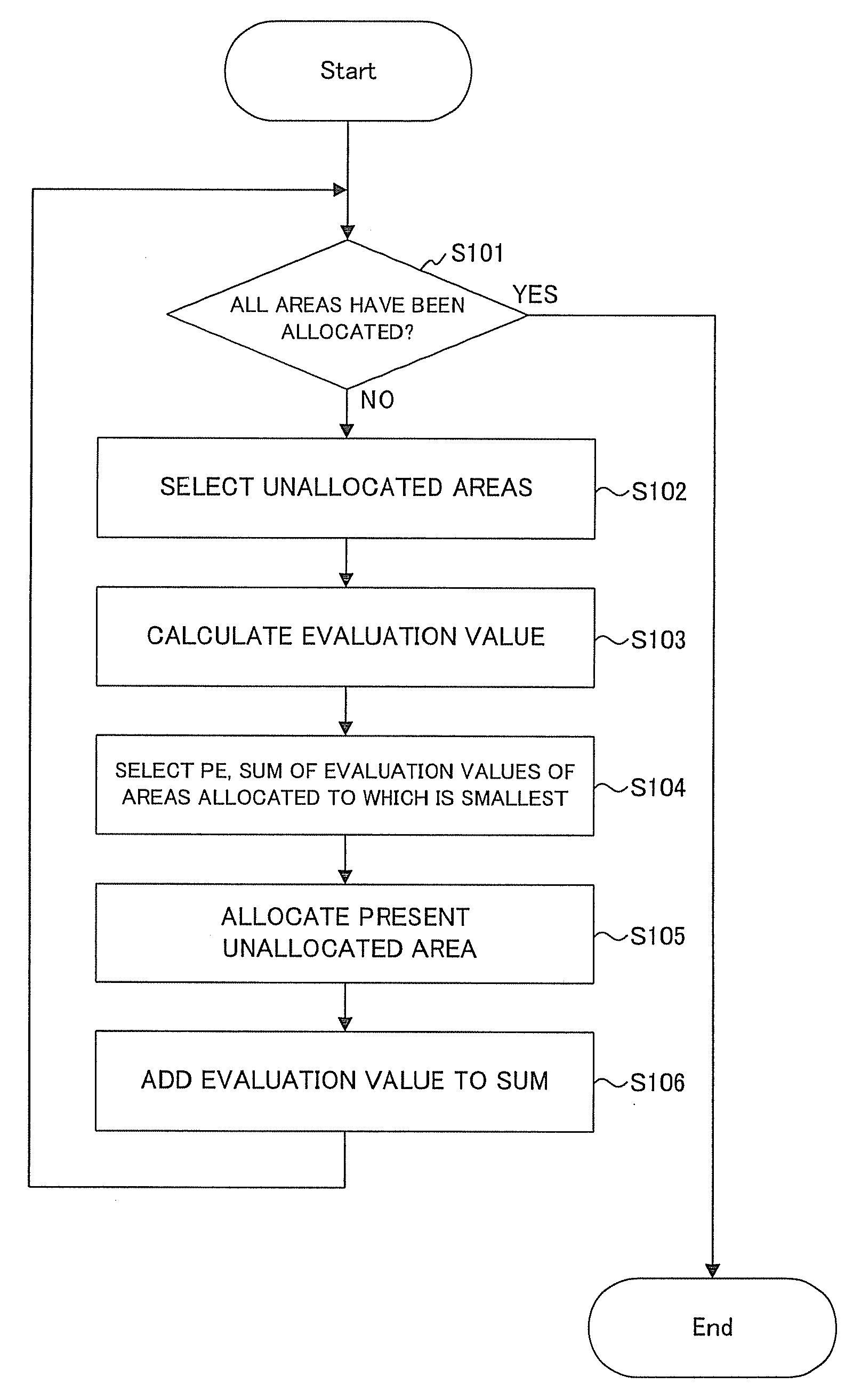
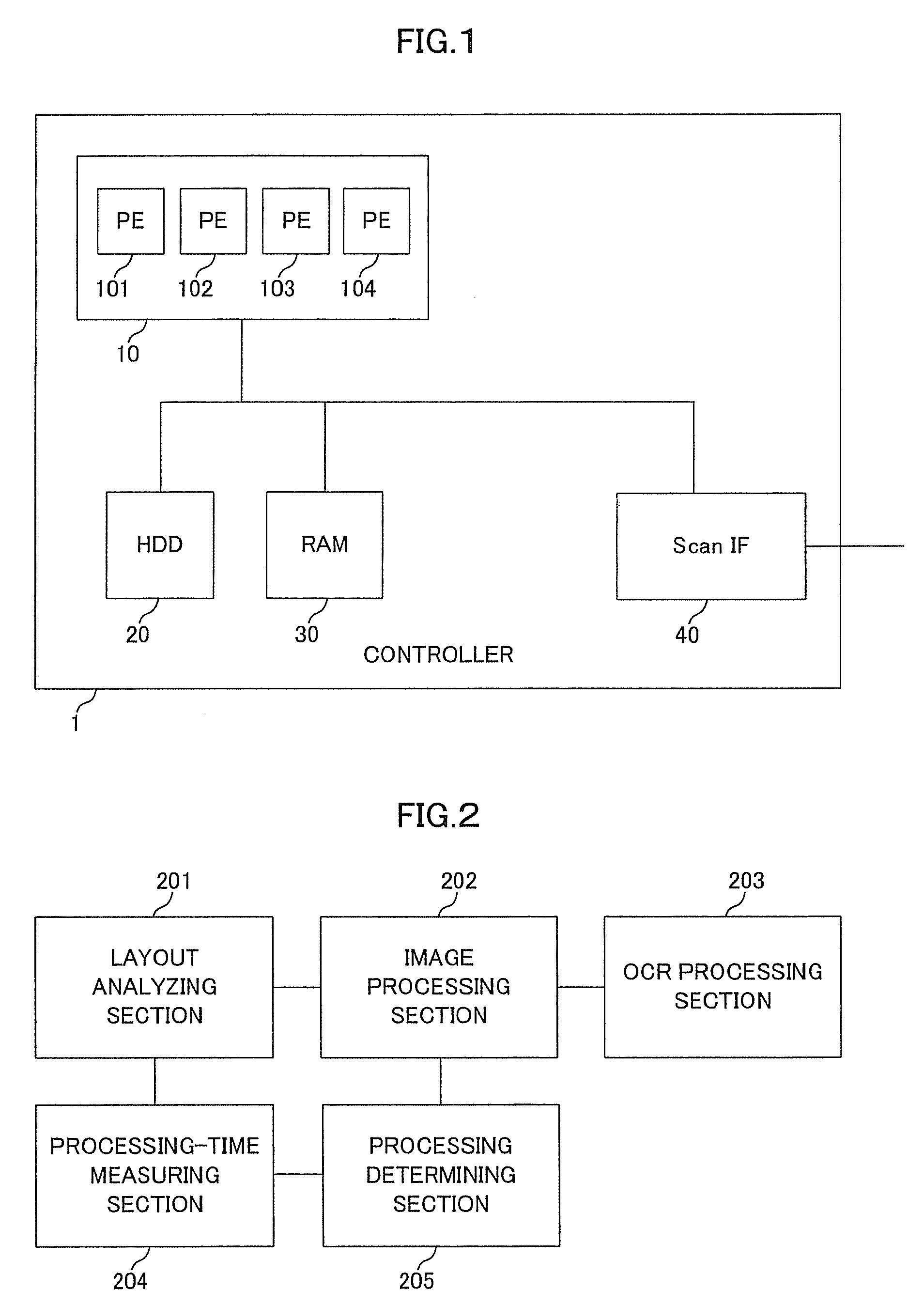
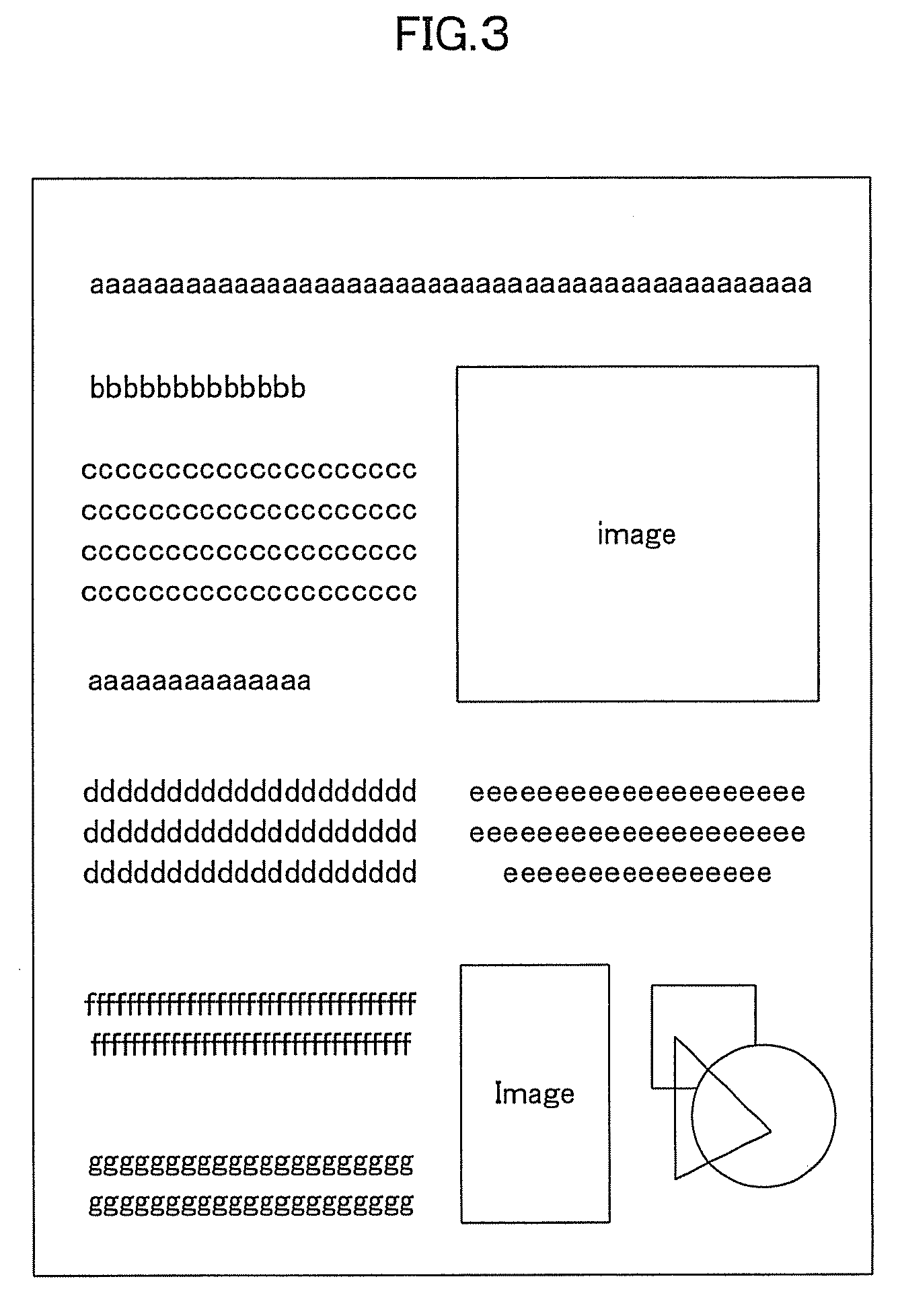
[0025]FIG. 1 is a block diagram showing a controller according to a first embodiment of the present invention.FIG. 2 is a functional block diagram in a processor according to the first embodiment. FIG. 3 is a diagram of image data analyzed in the first embodiment. FIG. 4 is a diagram of an analysis result of the image data in the first embodiment. FIG. 5 is a table showing an example of a calculation of evaluation values for parameters. FIG. 6 is a diagram showing an example of scheduling for processing.

[0026]As shown in FIG. 1, a controller 1 is a controller (an image processing apparatus) for controlling an MFP (Multifunction Printer; an image forming apparatus) and includes a processor 10 (plural processors), an HDD (Hard Disk Drive) 20, a RAM (Random Access Memory) 30, and a scan IF (interface) 40 (an image-data receiving section). The processor 10 performs image processing and processing for control of the MFP. The HDD 20 stores settings, programs, and the like for the image pr...

second embodiment

[0048]A second embodiment of the present invention is explained.

[0049]This embodiment is different from the first embodiment in that a degree of importance as a weighting coefficient is added to respective parameters for compression and OCR processing for each of areas and an evaluation value of processing for the area is calculated by taking into account the degree of importance. According to the difference from the first embodiment, components and operations for functions executed on the processing processor 10 are different from those in the first embodiment. The components and the operations different from those in the first embodiment are explained below. FIG. 8 is a functional block diagram in a controller according to the second embodiment. FIG. 9 is a diagram showing an example of degrees of importance added to the respective parameters.

[0050]As shown in FIG. 8, the processor 10 is different from that according to the first embodiment in that the processor 10 includes, in ad...


PUM


Abstract

An image forming apparatus that processes image data using plural processors that operate in parallel includes an image-data receiving section that receives inputted image data, a layout analyzing section that analyzes a layout structure including a predetermined area on the basis of the image data received by the image-data receiving section, a processing-amount calculating section that calculates a processing amount for the predetermined area in the layout structure of the image data analyzed by the layout analyzing section, and a processing-processor determining section that allocates, in processing for all areas in the layout structure analyzed by the layout analyzing section, processing for the predetermined areas to any one of the plural processors on the basis of the processing amount calculated by the processing-amount calculating section.

Description

BACKGROUND OF THE INVENTION[0001]1. Field of the Invention[0002]The present invention relates to a scheduling technique for plural processors in a layout analysis.[0003]2. Description of the Background[0004]Conventionally, there is known a technique for analyzing, in a function of scanning a paper document with a scanning function of an MFP to create an electric document, a layout of scanned image data to thereby extract a character area, a background area, an image area, and the like and selecting a compression method most suitable for the respective extracted areas to simultaneously realize improvement of efficiency of compression of scanning data and visibility. This technique is a technique, for example, for an area extracted as the character area by the layout analysis the shape of the character is compressed using binary compression techniques such as MMR, JBIG, or JBI2 and an area extracted as the background area or an image area such as a photograph or a picture by the layou...

Claims


Application Information

Patent Timeline
IPC IPC(8): G06K9/34
CPCG06K9/00993G06V10/96
Inventor HIRABAYASHI, KAZUNORI
Owner KK TOSHIBA
Features
  • R&D
  • Intellectual Property
  • Life Sciences
  • Materials
  • Tech Scout
  • Unparalleled Data Quality
  • Higher Quality Content
  • 60% Fewer Hallucinations
Learn More