

Image forming device
- Summary
- Abstract
- Description
- Claims
- Application Information
AI Technical Summary
Benefits of technology
Problems solved by technology
Method used
Image

Examples
example 1
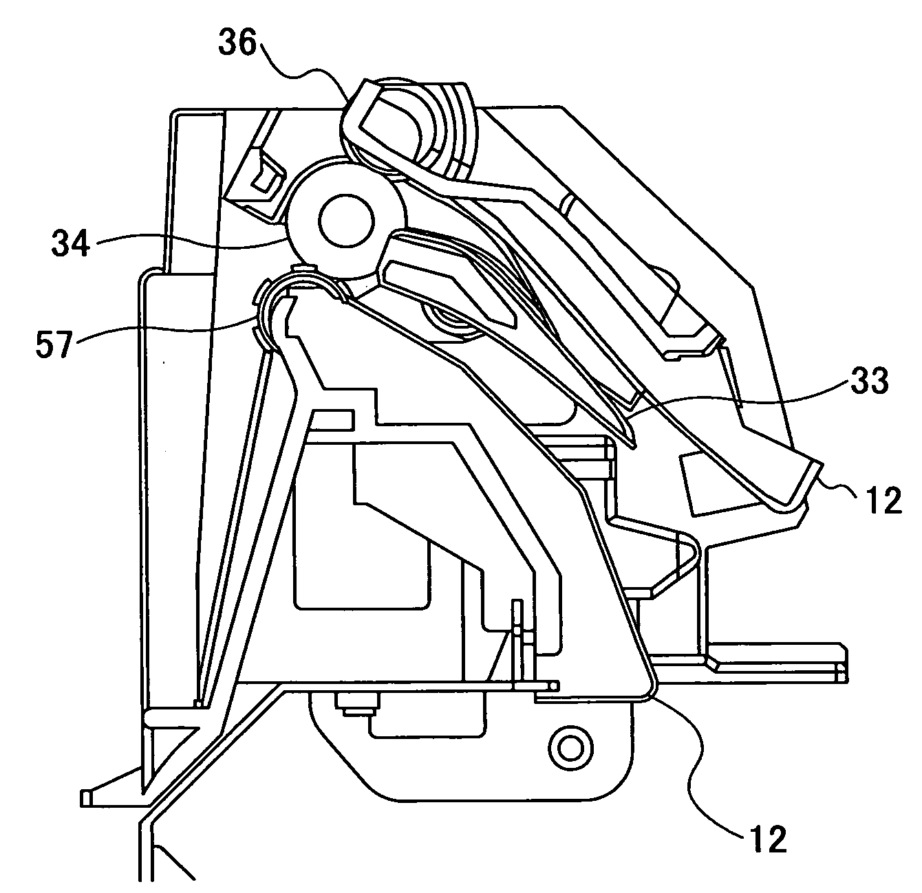
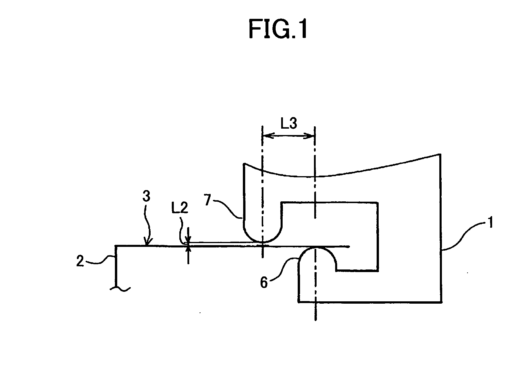
[0089]In the present example, as shown in FIG. 1, the solenoid fixing member 1 has a protruding shape 6, which is arranged to touch the bottom face of a top-face section 3 of the body frame 2 when assembling the paper output apparatus 9 to the body frame 2. In this way, arranging for the protruding shape 6 to touch the bottom face of the top-face section 3 of the body frame 2 makes it possible to position the gear housing 11 relative to the device body such that the position of the paper-output side delivery gear 4 of the gearing housing 11 on which the solenoid fixing member 1 is mounted is made proper relative to the fixing-side delivery gear 5 of the fixing apparatus 10 that is positioned to the device body. In other words, when the paper-output apparatus 9 is assembled to the device body, the protruding shape 6 serves as a stopper for ensuring that the difference between an intercentral distance L1 between the fixing-side delivery gear 5 and the paper-output side delivery gear 4...
example 2
[0096]In the present example, the configuration is basically the same as that of the Example 1, except that, as shown in FIG. 16, the distance of the gap between the protruding shape 6 and the protruding shape 7, which are formed at the solenoid-fixing member 1 is arranged to be a minimum distance within a range such that the top-face section 3 of the body frame 2 can be inserted into the gap, and the protruding shapes 7 and 6 touch the top and bottom faces of the top-face section 3 of the body frame 2, respectively. In this way, a positive or negative difference between the intercentral distance L1 between the fixing-side delivery gear 5, which the fixing apparatus 10, positioned relative to and assembled to the device body, has, and the paper-output delivery gear 4 of the gear housing 11 to which the solenoid-fixing member 1 is mounted, is suppressed in a more ensured manner.
embodiment 2
[0097]The basic configuration of the image forming device according to the present embodiment is substantially the same as that of the printer, which is the image forming device according to the Embodiment 1, so that the explanation thereof is omitted.
PUM
 Abstract
Description
Claims
Application Information