Fuel Cell System and Operating Method of Fuel Cell System

a fuel cell and operating method technology, applied in the field of fuel cell systems, can solve the problems of fuel cells falling into a state of insufficient gas supply, inability to design the gas pressure-feeding device free from such fluctuation in gas supply amount, and inability to achieve the control procedure, etc., to achieve the effect of maximizing the power generation amoun

Inactive Publication Date: 2009-04-30
TOYOTA JIDOSHA KK
View PDF3 Cites 13 Cited by
  • Summary
  • Abstract
  • Description
  • Claims
  • Application Information

AI Technical Summary

Benefits of technology

[0010]The operating method according to this aspect of the invention relatively increases the rate of the supply amount of the fluid to the power generation amount and supplies the fluid at this relatively increased rate to the fuel cells under the power generation control for satisfying the power generation demand. Namely the supply amount of the fluid actually supplied to the fuel cells exceeds a required supply amount of the fluid corresponding to the power generation demand. This arrangement effectively prevents the fuel cells from being operated in a state of insufficient fluid supply. In the case of power generation of the fuel cells with supply of the fluid at the supply amount corresponding to the power generation demand, the fuel cells are operated to obtain a power generation amount lower than the power generation demand. This also effectively prevents the fuel cells from being operated in the state of insufficient fluid supply. The operating method of the fuel cell system according to this aspect of the invention thus effectively prevents the fuel cells from being operated in the state of insufficient fluid supply by the simple increasing correction of the supply amount of the fluid based on the fluctuation in fluid supply or by the simple decreasing correction of the power generation amount based on the fluctuation in fluid supply.
[0012]In the fuel cell system according to this aspect of the invention, the corrected supply amount of the fluid by the increasing correction of the supply amount corresponding to the power generation demand is supplied to the fuel cells under power generation control for satisfying the power generation demand. The fuel cell system according to this aspect of the invention thus effectively prevents the fuel cells from being operated in the state of insufficient fluid supply by the simple increasing correction of the supply amount of the fluid based on the fluctuation in fluid supply.
[0014]In the fuel cell system according to this aspect of the invention, in the case of power generation of the fuel cells at a power generation amount corresponding to a supply amount of the fluid supplied to the fuel cells, the fuel cells are controlled to perform the power generation at the corrected power generation amount after the decreasing correction. The fuel cell system according to this aspect of the invention thus effectively prevents the fuel cells from being operated in the state of insufficient fluid supply by the simple decreasing correction of the power generation amount based on the fluctuation in fluid supply.
[0016]In the fuel cell system of this application, the supply amount of the fluid supplied to the fuel cells is subjected to the increasing correction based on the fluctuation in fluid supply. The power generation amount computed corresponding to the corrected supply amount of the fluid represents a maximum power generation amount with the supply amount of the fluid supplied to the fuel cells. The maximum power generation amount (the power generation amount computed corresponding to the corrected supply amount of the fluid after the increasing correction) is then subjected to the decreasing correction based on the fluctuation in fluid supply. When the corrected maximum power generation amount after the decreasing correction is smaller than the power generation demand, the operation of the fuel cells is controlled with the corrected maximum power generation amount after the decreasing correction. When the corrected maximum power generation amount is not smaller than the power generation demand, on the other hand, the operation of the fuel cells is controlled with the power generation demand. Compared with the conventional operation control of the fuel cells with the power generation demand, this arrangement effectively prevents the fuel cells from being operated in the state of insufficient fluid supply, while maximizing the power generation amount and ensuring generation of electric power to satisfy the power generation demand.

Problems solved by technology

Under power generation control to obtain a desired power generation amount with supply of a corresponding amount of the gas, the fluctuation in gas supply amount may causes the fuel cells to fall in a state of insufficient gas supply.
The design of the gas pressure-feeding device free from such fluctuation in gas supply amount is, however, impractical, because of its complicated structure and the requirement for extreme accuracy and precision of its constituents.
The procedure of such control, however, becomes undesirably complicated since consideration in time lag of the fluctuation is required.

Method used


Image

  • Fuel Cell System and Operating Method of Fuel Cell System
  • Fuel Cell System and Operating Method of Fuel Cell System
  • Fuel Cell System and Operating Method of Fuel Cell System

Examples


Embodiment Construction

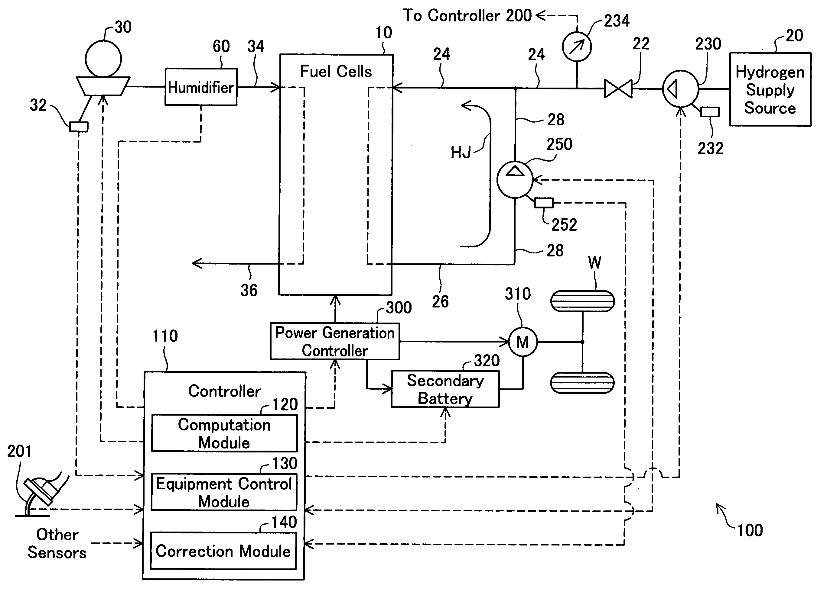
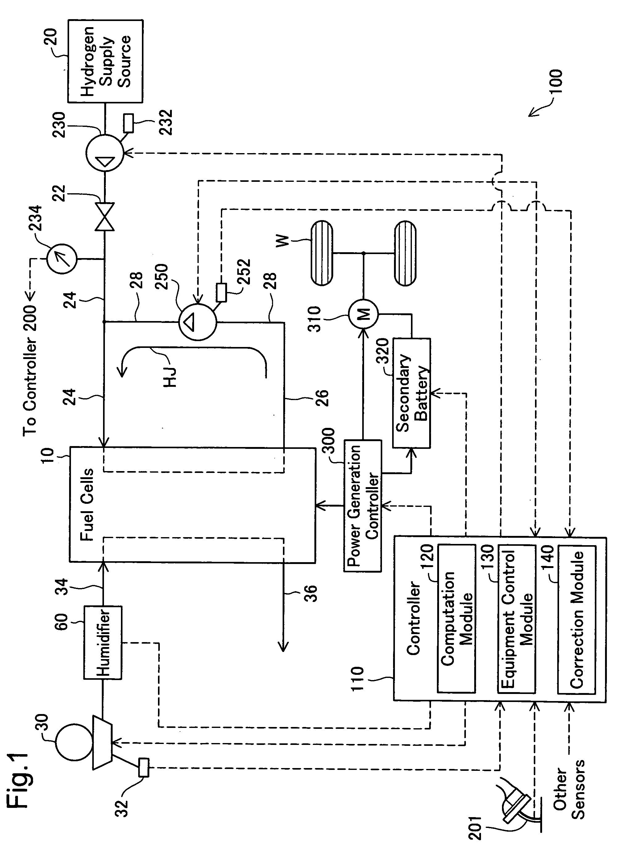
[0029]Some modes of carrying out the invention are described below with reference to the accompanied drawings. FIG. 1 is a block diagram schematically illustrating the configuration of a fuel cell system 100 according to one embodiment of the invention. The fuel cell system 100 mainly includes fuel cells 10, a hydrogen supply source 20, a blower 30, a controller 110, a humidifier 60, a circulation pump 250, and a power generation controller 300.

[0030]The fuel cells 10 are hydrogen separation membrane fuel cells and have a stack structure of multiple unit cells as constituent units. Each unit cell has a hydrogen electrode (hereafter referred to as anode) and an oxygen electrode (hereafter referred to as cathode) arranged across an electrolyte membrane. The fuel cells 10 generate electric power through an electrochemical reaction of a hydrogen-containing fuel gas (hereafter referred to as anode gas) supplied to the anodes of the respective unit cells with an oxygen-containing oxidizin...


PUM

PropertyMeasurementUnit
power generationaaaaaaaaaa
poweraaaaaaaaaa
electric poweraaaaaaaaaa

Abstract

In a fuel cell system equipped with a fluid supply device, such as a pump, in a fluid supply system to fuel cells, an insufficient supply of a fluid to the fuel cells is avoided by taking into account a fluctuation in fluid supply induced by operation of the fluid supply device. A procedure of gas supply to the fuel cells makes an increasing correction to increase supply amounts of hydrogen gas and the air according to a fluctuation in gas supply induced by operations of pumps and a blower, and actually supplies the hydrogen gas and the air of the corrected supply amounts after the increasing correction. The fuel cells are under power generation control to obtain a required power generation current equivalent to a power generation demand, while receiving the hydrogen gas supply and the air supply of corrected supply amounts by increasing correction of gas supply base amounts corresponding to the required power generation current.

Description

TECHNICAL FIELD[0001]The present invention relates to a fuel cell system including fuel cells and a supply device provided for supply of a fluid required for power generation by the fuel cells, as well as to an operating method of such a fuel cell system.BACKGROUND ART[0002]Fuel cells generally have a stack structure of multiple unit cells. In each unit cell, an MEA (membrane electrode assembly) including an electrolyte layer with catalyst layers formed on both faces thereof is interposed between gas flow path-forming members for a fuel gas and an oxidizing gas. In the fuel cells of this stack structure, separate gas supply systems are provided for the fuel gas and the oxidizing gas to be supplied to the respective unit cells. A gas pressure-feeding device, such as a compressor, a pump, or a blower, is generally provided in each gas supply system to pneumatically supply the fuel gas or the oxidizing gas (for example, the air).[0003]The level of power generation of the fuel cells is ...

Claims


Application Information

Patent Timeline
Patent Type & Authority Applications(United States)
IPC IPC(8): H01M8/04
CPCH01M8/04089H01M8/04097H01M8/04388H01M8/04395Y02E60/50H01M8/04753H01M8/0491H01M8/04992H01M8/04619H01M8/04
Inventor SAITO, TOMOHIROMATSUMOTO, TADAICHI
Owner TOYOTA JIDOSHA KK
Why Eureka
Try Eureka