Clutch control apparatus for vehicle

Active Publication Date: 2009-04-30
HONDA MOTOR CO LTD
View PDF12 Cites 9 Cited by
  • Summary
  • Abstract
  • Description
  • Claims
  • Application Information

AI Technical Summary

Benefits of technology

[0007]Accordingly, it is an object of the present invention to suppress a motion delay at the time of engaging a clutch to allow quick and smooth start and shifting in a clutch control apparatus for a vehicle provided with a hydraulic clutch in the middle of a power transmission path between an engine and a drive wheel.

Problems solved by technology

However, the clutch control apparatus described above may sometimes cause delay resulting from the effect of response of the solenoid valve during from the start of the clutch engagement motion to the actual clutch engagement state.
Thus, it is difficult to execute quick and smooth start and shifting.
In addition, its tendency is easily-noticeable, particularly, at the time of starting on the slope or of suddenly opening the throttle valve.

Method used


Image

  • Clutch control apparatus for vehicle
  • Clutch control apparatus for vehicle
  • Clutch control apparatus for vehicle

Examples


Embodiment Construction

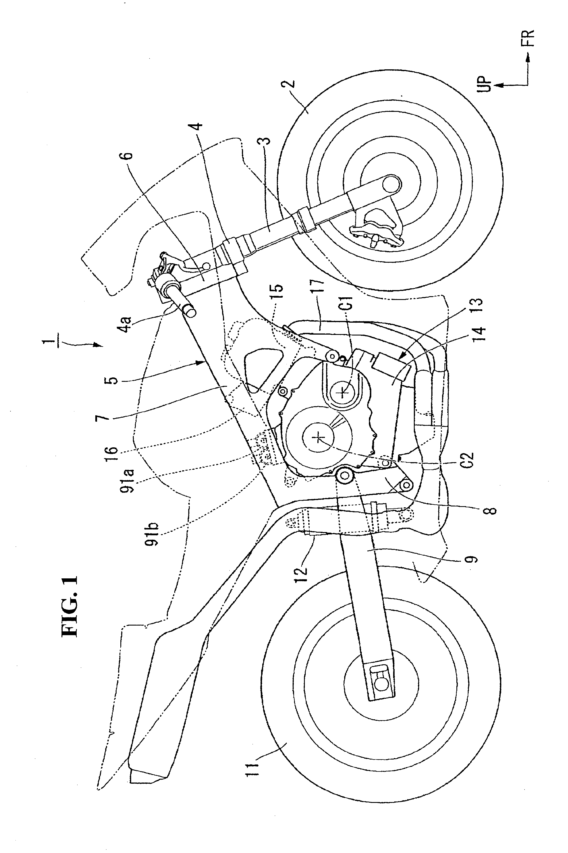
[0037]It is to be noted that orientations such as the front, back or rear, left, right, etc. in the following description are the same as that of a vehicle unless otherwise explained. In addition, arrows FR, LH, UP in the drawings denote the front, left and upside, respectively, of the vehicle.

[0038]With reference to FIG. 1, a front wheel 2 of a motorcycle (a saddle-ride type vehicle) 1 is rotatably supported by a front fork 3. The front fork 3 is steerably supported at its upper portion by a head pipe 6 via a steering stem 4. The head pipe 6 is located at the front end of a body frame 5. Steering handlebars 4a are attached to the upper portion of the steering stem 4 (or the front fork 3). A main frame 7 extends rearward from the head pipe 6 and connects with a pivot plate 8. The front end of a swing arm 9 is up and down swingably supported by the pivot plate 8. A rear wheel 11 is rotatably supported by the rear end of the swing arm 9. A shock absorber 12 is interposed between the s...


PUM


Abstract

A clutch control apparatus for a vehicle provided with a hydraulic clutch in the middle of a power transmission path between an engine and a drive wheel. Before the clutch of the vehicle is brought into an engagement state, intermittent hydraulic pressure Y is applied to the clutch while maintaining the clutch in a disengagement state, and thereafter a predetermined hydraulic pressure is applied to the clutch to bring it into the engagement state. A solenoid valve is provided to control hydraulic pressure supplied to the clutch. Before the clutch is brought into the engagement state, a pulsed drive current D is supplied to the solenoid valve. The clutch control apparatus so configured suppresses a motion delay at the time of engaging the clutch, thereby allowing a quick and smooth start and shifting of the clutch.

Description

CROSS-REFERENCE TO RELATED APPLICATION[0001]The present application claims priority under 35 U.S.C. §119 to Japanese Patent Application Nos. 2007-282182 and 2007-282183, both filed Oct. 30, 2007, the entire contents of which are hereby incorporated by reference.BACKGROUND OF THE INVENTION[0002]1. Field of the Invention[0003]The present invention relates to a clutch control apparatus for a vehicle.[0004]2. Description of Background Art[0005]Conventionally, there is known a clutch control apparatus for a vehicle provided with a hydraulic clutch that is disposed in the middle of a power transmission path between an engine and a drive wheel and brought into an engagement state by hydraulic pressure supplied from the outside. This apparatus supplies a pulsed drive current to a solenoid valve adapted to control hydraulic pressure supplied to the clutch, in order to gradually bring the clutch into the engagement state (see e.g. Japanese Patent Laid-open No. Sho 59-219549, and Japanese Util...

Claims


Application Information

Patent Timeline
IPC IPC(8): F16H59/24F16D25/00F16H61/26
CPCF16D48/062F16D48/066F16D2500/1027F16D2500/10412F16D2500/1117F16D2500/3063Y10T477/6936F16D2500/50684F16D2500/70406F16D2500/7109Y10T477/69365Y10T477/693Y10T477/6937F16D2500/5063
Inventor FUKAYA, KAZUYUKIOZEKI, TAKASHITSUKADA, YOSHIAKIKOJIMA, HIROYUKINEDACHI, YOSHIAKI
Owner HONDA MOTOR CO LTD
Why Eureka
Try Eureka