Video system, video transmitter, video receiver and control method for the same

a video system and video receiver technology, applied in the field of video systems, can solve the problems of increased hardware cost and complex circuit layout, and achieve the effect of simplifying circuit layout and reducing hardware cos

Inactive Publication Date: 2009-04-30
AVTECH
View PDF4 Cites 340 Cited by
  • Summary
  • Abstract
  • Description
  • Claims
  • Application Information

AI Technical Summary

Benefits of technology

[0018]The present invention is proposed inserting the control signal into the video signal and transmitting the video signal with the control signal through a coaxial-cable, and thereby eliminate the need of an transmission terminal (ex: RS-232 cable) for transmitting the control signal. In such a way, the cost of the hardware can be reduced and the circuit layout can be simplified. In the other hand, the present invention proposes transmitting the control signal by adjusting the impedance values of the transmission interface to achieve a bi-directional transmission function through a coaxial-cable.

Problems solved by technology

Accordingly, cost of hardware is increased, and circuit layout is complex.

Method used


Image

  • Video system, video transmitter, video receiver and control method for the same
  • Video system, video transmitter, video receiver and control method for the same
  • Video system, video transmitter, video receiver and control method for the same

Examples


Embodiment Construction

[0028]Reference will now be made in detail to the present preferred embodiments of the invention, examples of which are illustrated in the accompanying drawings. Wherever possible, the same reference numbers are used in the drawings and the description to refer to the same or like parts.

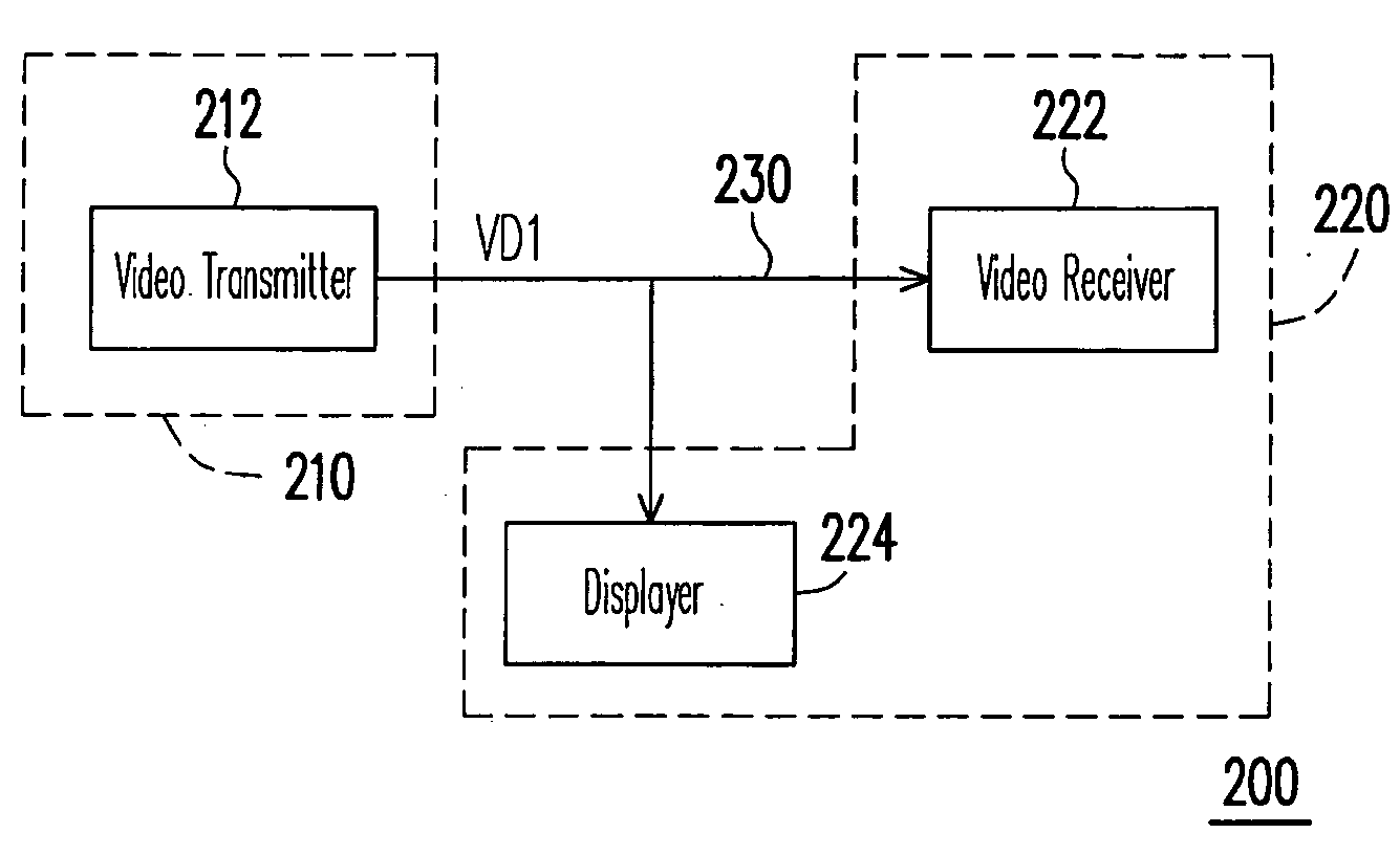
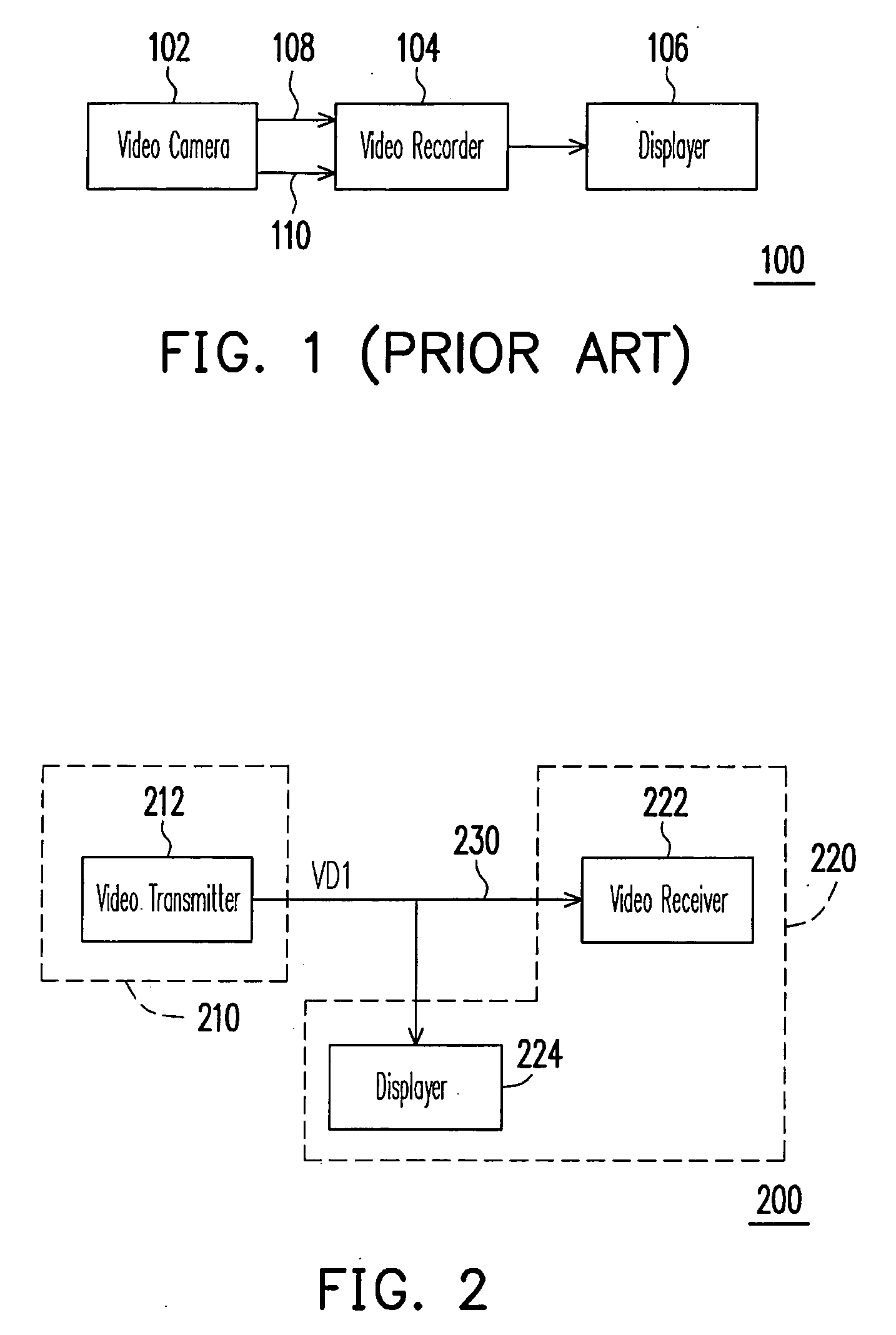
[0029]FIG. 2 is a block diagram illustrating a video system according to an embodiment of the present invention. Referring to FIG. 2, the video system 200 includes an transmitting terminal 210, and a receiving terminal 220. The transmitting terminal 210 and the receiving terminal 220 are coupled one to another via a transmission interface 230. According to an aspect of the embodiment, the transmission interface 230 is a coaxial cable.

[0030]The transmitting terminal 210 includes an video transmitter 212 (e.g. NTSC or PAL camera system). The transmitting terminal 210 is adapted for transmitting a video signal VD1 with a control signal to the receiving terminal 220 via the transmission interface 230. Th...


PUM


Abstract

A video system with a bi-directional transmission function is provided. The video system includes an video transmitter, a transmission interface and a video receiver. The video transmitter is coupled to the video receiver via the transmission interface (coaxial cable). The video transmitter is used for inserting a first control signal into the video signal according a synchronous signal of the video signal. The video transmitter is used for outputting the video signal with the first control signal to the video receiver via the transmission interface. The video receiver receives the video signal with the first control signal, and gets the first control signal from the video signal according to the synchronous signal of the video signal. In addition, the video receiver can insert a second control signal into the video signal and feedback the second control signal to the video transmitter via the transmission interface.

Description

CROSS-REFERENCE TO RELATED APPLICATION[0001]This application claims the priority benefit of Taiwan application serial no. 96140805, filed on Oct. 30, 2007. The entirety of the above-mentioned patent application is hereby incorporated by reference herein and made a part of specification.BACKGROUND OF THE INVENTION[0002]1. Field of the Invention[0003]The present invention generally relates to a video system, and more particularly, to a video system with a bi-directional transmission function.[0004]2. Description of Related Art[0005]FIG. 1 is a block diagram illustrating a conventional video system. Referring to FIG. 1, the video system 100 includes a video camera 102, a video recorder 104, and a display 106. The video camera 102 (e.g. NTSC or PAL camera system) is used for capturing a object and generating a video signal. The video camera 102 outputted the video signal to the video recorder 104 through the coaxial cable 108. The video recorder 104 can store the video signal captured b...

Claims


Application Information

Patent Timeline
Patent Type & Authority Applications(United States)
IPC IPC(8): H04N7/173
CPCH04N5/77H04N5/775H04N7/10H04N7/083H04N7/088H04N5/781H04N5/38H04N21/426
Inventor TSENG, YUAN-LIANGLING, HSUEH-SHEN
Owner AVTECH
Why Eureka
Try Eureka