Photo-Acoustic Flow Meter

a flow meter and photo-acoustic technology, applied in the direction of volume/mass flow measurement, measurement devices, instruments, etc., can solve the problems of invasiveness, non-invasive or non-contact measurement of the flow rate of fluid in the prior art flow meter

Inactive Publication Date: 2009-05-07
FRESENIUS MEDICAL CARE HLDG INC
View PDF101 Cites 99 Cited by
  • Summary
  • Abstract
  • Description
  • Claims
  • Application Information

AI Technical Summary

Problems solved by technology

These aforementioned prior art flow meters are invasive; in other words, these flow meters or some mechanical parts thereof are required to be in contact with the fluid for which the flow rate is to be determined.
However, non-invasive or non-contact measurement of rate of flow of...

Method used


Image

  • Photo-Acoustic Flow Meter
  • Photo-Acoustic Flow Meter
  • Photo-Acoustic Flow Meter

Examples


Embodiment Construction

[0016]While the present invention may be embodied in many different forms, for the purpose of understanding of the principles of the invention, reference will now be made to the embodiments illustrated in the drawings and specific language will be used to describe the same. It will nevertheless be understood that no limitation of the scope of the invention is thereby intended. Any alterations and further modifications in the described embodiments, and any further applications of the principles of the invention as described herein are contemplated as would normally occur to one skilled in the art to which the invention relates.

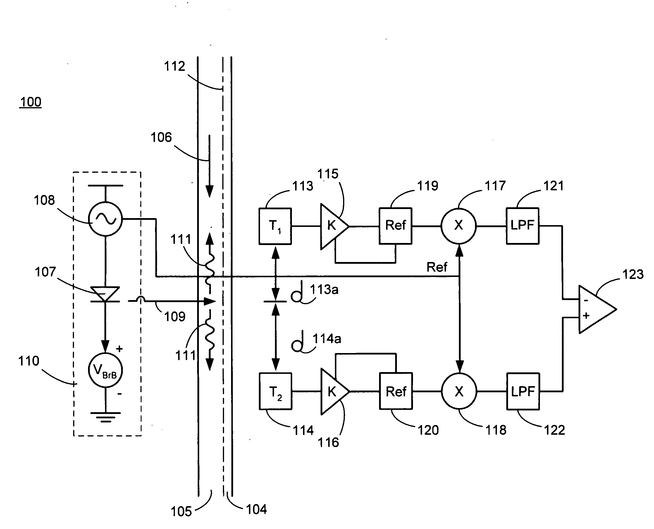
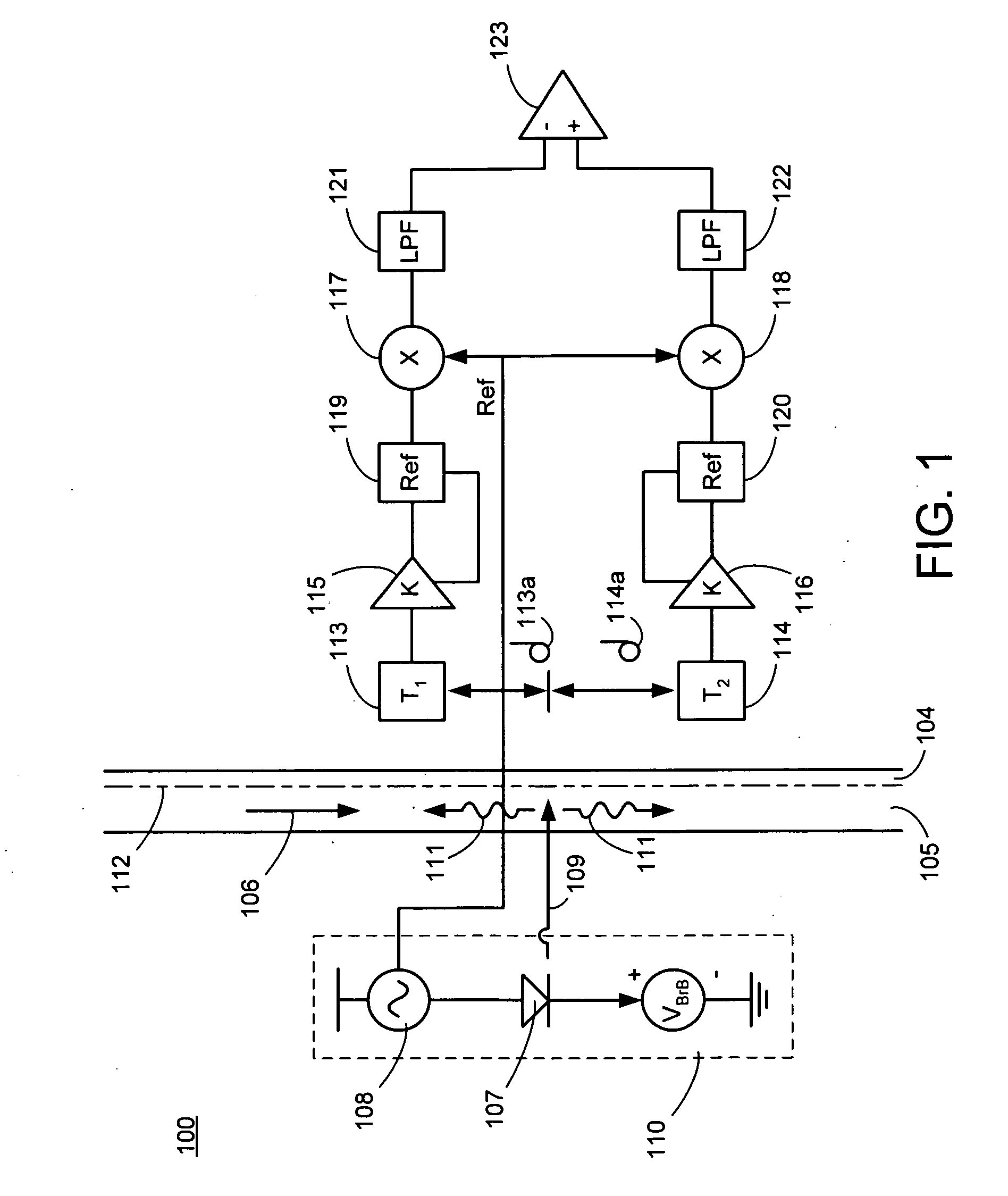
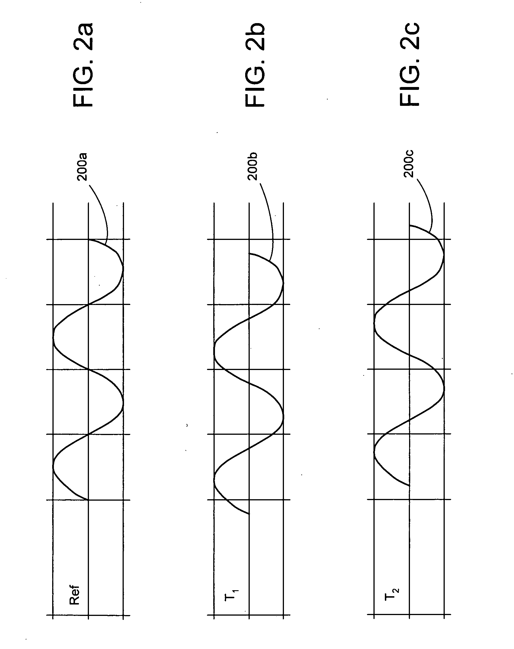
[0017]The present invention is a novel non-invasive or non-contact type acoustic flow meter that has the ability to generate an acoustic signal directly in the fluid to be monitored without physical contact. The acoustic flow meter of the present invention provides flow measurement with improved accuracy, based on the measurement of acoustic wave transit time. ...


PUM


Abstract

A photo-acoustic flow meter for use in dialysis is described, that uses an optical beam to generate an acoustic signal in the fluid for which the flow rate is to be measured. The phase angle of the acoustic signal changes when traversing upstream and when traversing downstream. The phase difference between the acoustic signals received upstream and downstream, compared with a reference source signal is measured, and it yields the flow rate of the fluid.

Description

CROSS-REFERENCE[0001]The present invention relies upon U.S. Patent Provisional Application No. 60 / 979,113, filed on Oct. 11, 2007, for priority.FIELD OF THE INVENTION[0002]The present invention generally relates to the field of systems and methods for fluid flow rate measurement, and, more specifically, to a non-invasive acoustic fluid flow meter.BACKGROUND OF THE INVENTION[0003]Acoustic fluid flow meters operate based upon the principle that the propagation velocity of an acoustic wave in a fluid is a) equal to the acoustic velocity with respect to the fluid plus the velocity of the fluid in the direction of the flow and b) equal to the acoustic velocity with respect to the fluid minus the velocity of the fluid in the direction opposite to the direction of flow of the fluid. Typically, prior art acoustic flow meters include a pair of acoustic transducers each adapted for generating and detecting an acoustic pressure wave in a fluid, the velocity of which is to be measured. The tran...

Claims


Application Information

Patent Timeline
IPC IPC(8): G01F1/66
CPCG01F1/667
Inventor SMITH, MARK FORREST
Owner FRESENIUS MEDICAL CARE HLDG INC
Why Eureka
Try Eureka