Method of Treating Flow Conduits and Vessels with Foamed Composition

a flow conduit and composition technology, applied in the direction of cleaning hollow objects, chemistry apparatus and processes, borehole/well accessories, etc., can solve the problems of reducing the permeability of the subterranean formation, contaminant formation in equipment and flow conduits, and undesirable substances such as salt, scales, paraffins and asphaltenes, etc., to achieve low liquid volume and lower hydrostatic loading

Inactive Publication Date: 2009-05-07
BAKER HUGHES INC
View PDF19 Cites 70 Cited by
  • Summary
  • Abstract
  • Description
  • Claims
  • Application Information

AI Technical Summary

Benefits of technology

[0012]Use of the foamed treatment composition described herein is particularly advantageous since its liquid volume is low compared to its bulk volume. As a result, a foam quality greater than 90 percent is possible. Such low liquid volumes are advantageous due to economic savings in the volume of treatment agent. When used in gas or oil wells, such low liquid volumes impart a lower hydrostatic loading in the well.
[0013]The foam used in the foamed treatment composition is self-supporting. The foamed treatment composition is capable of completely packing the annular area of the well as well as covering the surface of a flow conduit or vessel.

Problems solved by technology

Such contaminants also form in equipment and flow conduits used in gas production and oil production as well as in refineries and fluid processing facilities.
Such undesirable substances as salt, scales, paraffins and asphaltenes form due to the pressure changes at the perforations.
The formation and deposition of such contaminants decrease permeability of the subterranean formation and reduce well productivity.
For instance, in some completions, the presence of scale in the annulus may make it difficult or impossible to remove the tubing for servicing.
In addition to being formed in oil and gas wells, such contaminants further form in equipment and flow conduits used in the production of oil, gas and other fluids.
For instance, an acute problem develops when such contaminants develop in equipment and flow conduits used in gas and oil production, refineries and other fluid processing facilities.
While there are a number of approaches to the inhibition and / or removal of contaminants in the patent and journal literature, nearly all of them deal with the problem on an individual basis as they form, which can be costly when numerous problems arise during operations.
A further problem with such an approach is the cost of tracking and monitoring the effectiveness of the selected approach.
However, the overflush process often flushes a significant portion of the treatment agent such the remaining treatment agent is gradually removed from the surface as oil production continues.
Thus, further descaling treatments are typically required.
Treatment methods of the prior art are typically inefficient in that contact with all surfaces containing the contaminants is typically required though often not completely attained.
In addition, large quantities of the treatment agent are often required in order to effectuate the desired result.

Method used


Image

  • Method of Treating Flow Conduits and Vessels with Foamed Composition
  • Method of Treating Flow Conduits and Vessels with Foamed Composition
  • Method of Treating Flow Conduits and Vessels with Foamed Composition

Examples


examples 1-4

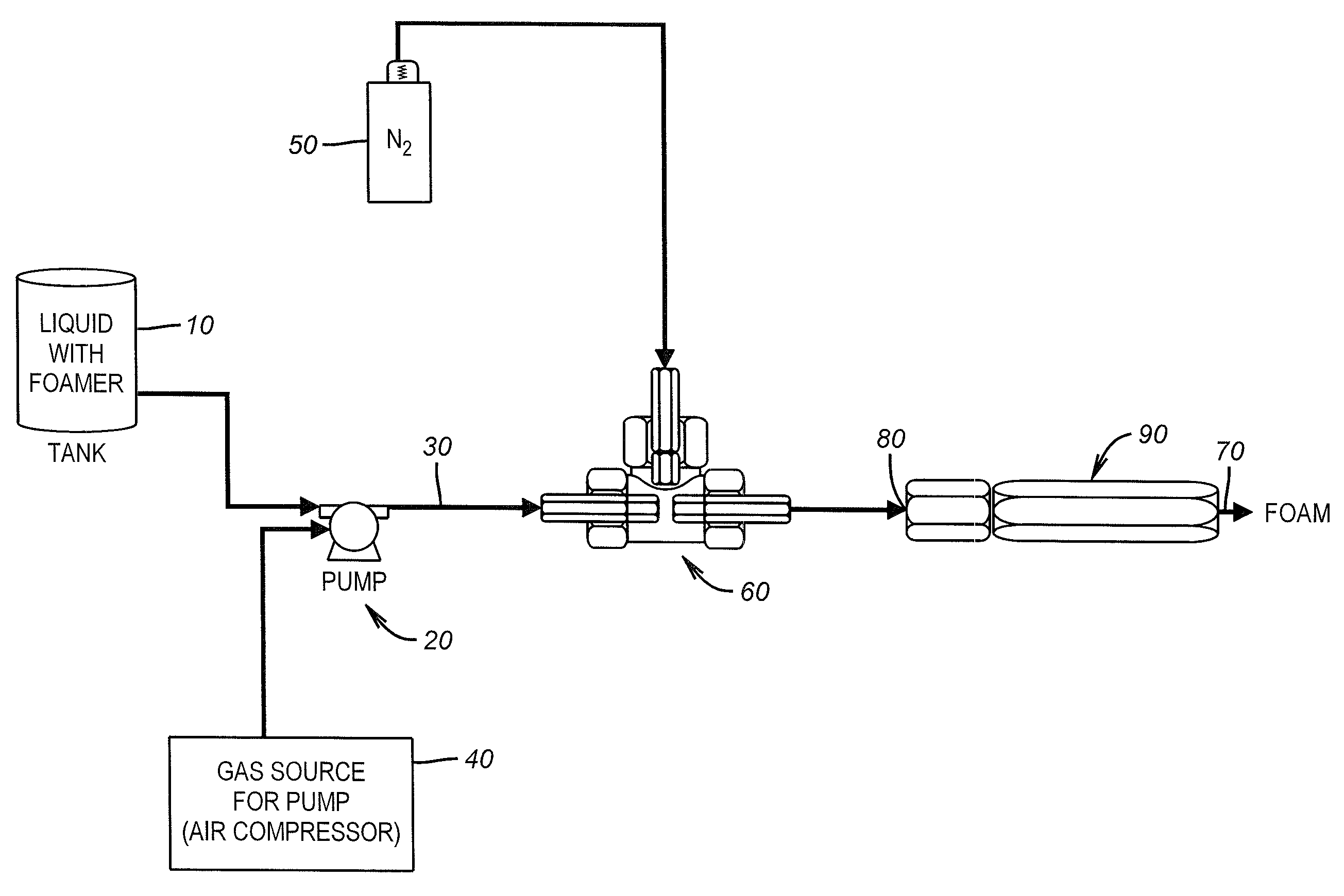
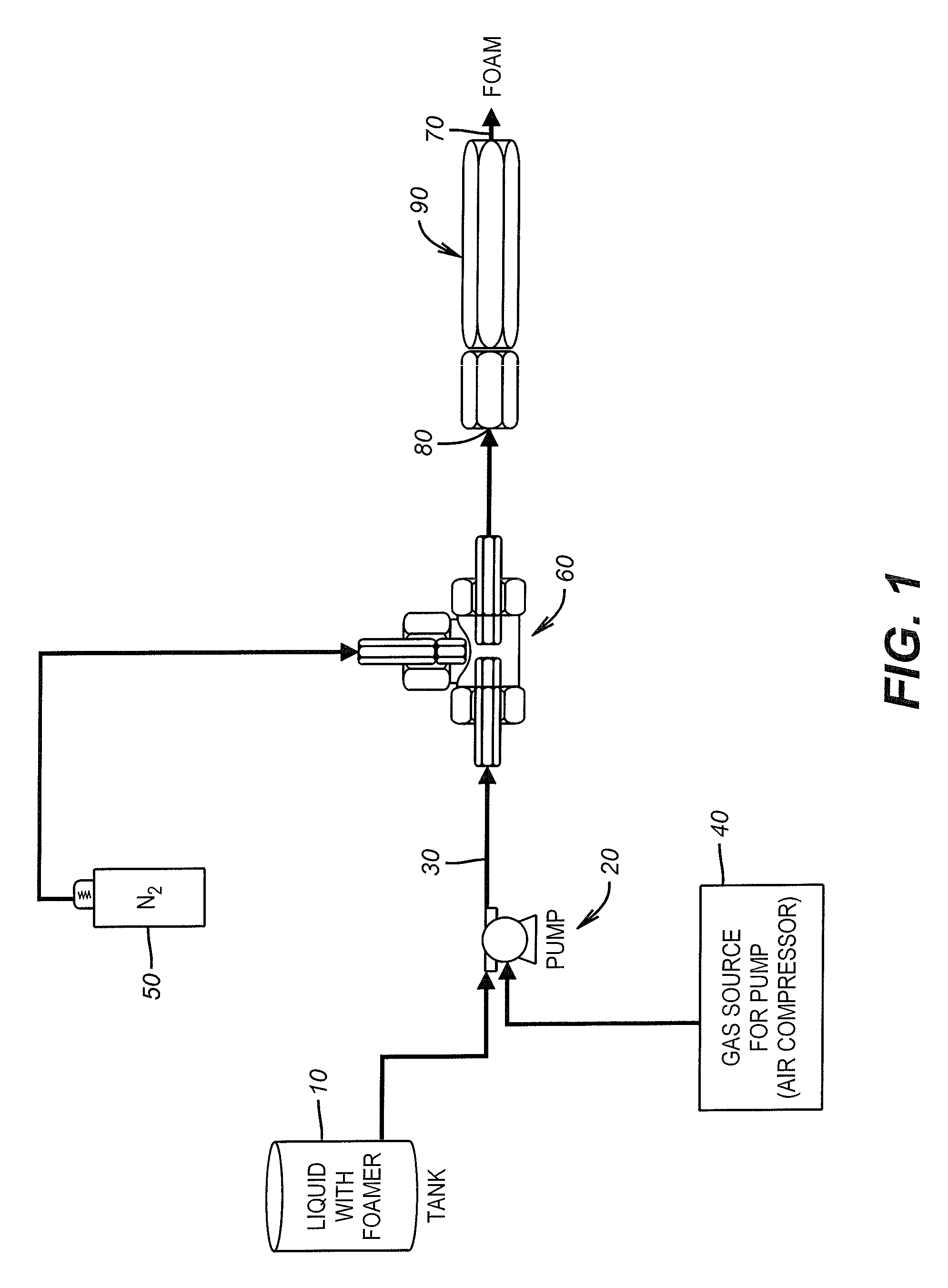
[0052]To a foaming agent composed of 60% C14-C15 alkyl olefin sulfate, 18% ammonium alkyl ether sulfate, 10% monoalkyl ester and 12% isopropyl alcohol was added a treatment agent (WTA), water and nitrogen. The admixture was then foamed using the foaming apparatus set forth in FIG. 1. The foam quality of the foamed product was then determined. The results are set forth in Table I:

TABLE IFoamingN2 Agent,WTA,Pressure,FoamEx. No.AmountType, WTAWTAAmountWaterpsiQuality, %1120 mlsScale RemoverHCl, 28%140 mls12,000 mls40952120 mlsScale RemoverHCl, 28% 1 qt5 gallons609732%Scale InhibitorHEDP 6%Yes609542%Scale InhibitorHEDP12%Yes6097HEDP = (hydroxethylidenediphosphonic acid)

examples 5-9

[0053]The foamed treatment composition of Example 4 was introduced into an annulus at defined pressure. The residual concentration of treatment agent was measured in produced water. The results are set forth in Table II:

TABLE IICasingTubingInjectionTime toResidualEx.Pressure,Pressure,Pressure,Pump,Liquid Volume,AfterNo.psipsiNitrogen, psipsihrs:mingallonsOne Month518680181:1536NA6294080291:202931.82 ppm714075142:2042145.29 ppm 85080202:1538116.7 ppm920075254:004326.25 ppm

example 10

[0054]A corrosion inhibitor was prepared by mixing 65.70 ml of deionized water, 25 ml of coco-dimethyl benzyl quat, 8 ml of complex organic phosphate ester, free acid, 0.2 ml of thioglycolic acid and 1.10% of monoethanolamine. Approximately 1 gallon of the corrosion inhibitor was mixed with 1 gallon of water and was then mixed with 1.5% of amphoteric cocoamidopropyl betaine as foaming agent to render 60 gallons of foam.


PUM

PropertyMeasurementUnit
pressureaaaaaaaaaa
pressureaaaaaaaaaa
volumeaaaaaaaaaa

Abstract

The annular surface between the tubing and casing of an oil or gas well as well as flow conduits and vessels may be contacted with a foamed treatment composition containing a gas, a foaming agent and a treatment agent. The treatment agent may be an inhibitor or removal agent for scales, corrosion, salts, paraffins or asphaltenes. The foam, upon destabilization, renders a thin film of concentrated treatment agent on the external surfaces of the tubing, inside the casing and in the perforations of the oil or gas well or on the flow conduits or vessels.

Description

[0001]This application is a continuation-in-part application of U.S. patent application Ser. No. 11 / 714,683, filed on Mar. 6, 2007.FIELD OF THE INVENTION[0002]Unwanted contaminants may be inhibited and / or removed by introducing a foamed composition containing a treatment agent into a gas or oil well. The foamed composition may further be used to inhibit and / or remove contaminants in equipment and flow conduits used in gas or oil production, refineries or fluid processing facilities.BACKGROUND OF THE INVENTION[0003]Oilfield fluids (e.g., oil, gas, and water) are generally complex mixtures of aliphatic hydrocarbons, aromatics, hetero-atomic molecules, anionic and cationic salts, acids, sands, silts, clays and a vast array of other components. The nature of these fluids, combined with the severe conditions of heat, pressure, and turbulence to which they are often subjected, are contributory factors to the formation and deposition of contaminants, such as scales, salts, paraffins, corro...

Claims


Application Information

Patent Timeline
Patent Type & Authority Applications(United States)
IPC IPC(8): C23G1/02B08B9/027C23G1/00
CPCE21B37/06C09K8/52
Inventor BROWN, JAMES MICHAELDARBY, JOHN GREGORY
Owner BAKER HUGHES INC
Why Eureka
Try Eureka