Pneumatic tire

Active Publication Date: 2009-05-07
YOKOHAMA RUBBER CO LTD
View PDF4 Cites 10 Cited by
  • Summary
  • Abstract
  • Description
  • Claims
  • Application Information

AI Technical Summary

Benefits of technology

[0018]The pneumatic tire according to the present invention includes the straight main groove and the two wave-shaped main grooves. The straight main groove is arranged in the center area of its tread and extends in the tire circumferential direction. The wave-shaped main grooves extend in the tire circumferential direction respectively at the two sides of the straight main groove, and the groove wall of each wave-shaped main groove curves in the form of a wave. Accordingly, like the existing type of pneumatic tire, the pneumatic tire according to the present invention has both good drainage performance and good noise performance against columnar resonance. Further, the pneumatic tire according to the present invention has improved driving stability, since in each shoulder area, the diagonal grooves extending obliquely outward from the wave-shaped main groove in the direction reverse to the tire rotational direction are each formed so as to have a convex arc shape protruding toward the outer side of the tire, and the extending end portion of each of the diagonal grooves terminates in the shoulder area, thus forming the pattern in each shoulder area as the non-block pattern in which the land section continues in the tire circumferential direction, and thereby increasing the rigidity in each shoulder area.
[0019]Furthermore, since each diagonal groove is formed so as to have a convex arc shape protruding toward the outer sid

Problems solved by technology

A pneumatic tire with such straight main grooves has improved drainage performance, but suffers from the following problems.
First, the straight main grooves cause a large columnar resonance while the tire is being run, and accordingly worsens noise performance.
Second, since the straight main grooves each having the wide groove width are arranged even in the respective shoulder areas, the rigidity of each shoulder area decreases, and the driving stability accordingly decreases.
However, the above-describe

Method used


Image

  • Pneumatic tire
  • Pneumatic tire
  • Pneumatic tire

Examples


Example

[0056]Four test tires according to each of Comparative Example, Example 1 and Example 2 were mounted on the respective rims (size: 18×8.5JJ) with an air pressure of 230 kPa, and attached to the four wheels of an automobile with an engine of 2.0-litre. Thereafter, for each of Comparative Example, Example 1 and Example 2, five trained test drivers evaluated the driving stability by a sensory test according to a five-point evaluation method while driving on a test course. The driving stability was evaluated for each of the examples with an average of evaluation values representing the respective five drivers' evaluations, and the results of the evaluations of Examples 1 and 2 were shown while indexing the result of the evaluation of Comparative Example as 100. A larger index value means better driving stability.

(Uneven Wear Resistance)

[0057]Four test tires according to each of Comparative Example, Example 1 and Example 2 were mounted on the respective rims (size: 18×8.5JJ) with an air ...

Example

Example 1

[0061]

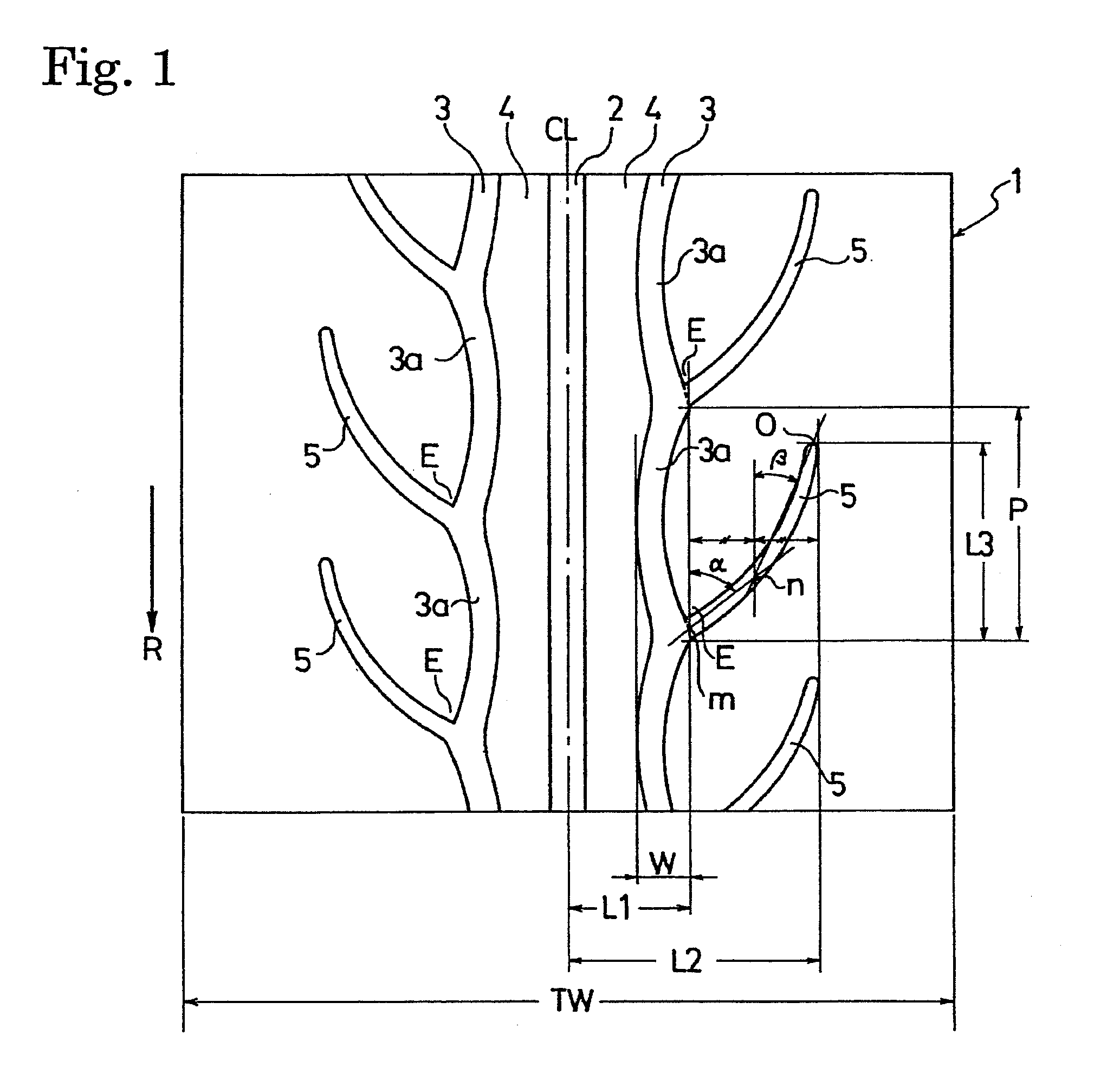
Tread PatternFIG. 1Groove Width of Straight12.7 mm Main Groove 2Groove Width of Wave-shaped9.5 mmMain Groove 3Pitch Length P of Wave-shaped57 mm to 83 mmMain Groove 3 (Arc-shapedGrooves)Number of Pitches of24 Wave-shaped Main Groove 3(Arc-shaped Grooves)Groove Width of Diagonal5.0 mmGroove 5Average Oblique Angle α of55°Diagonal Groove 5Average Oblique Angle β of27°Diagonal Groove 5

Example

Example 2

[0062]

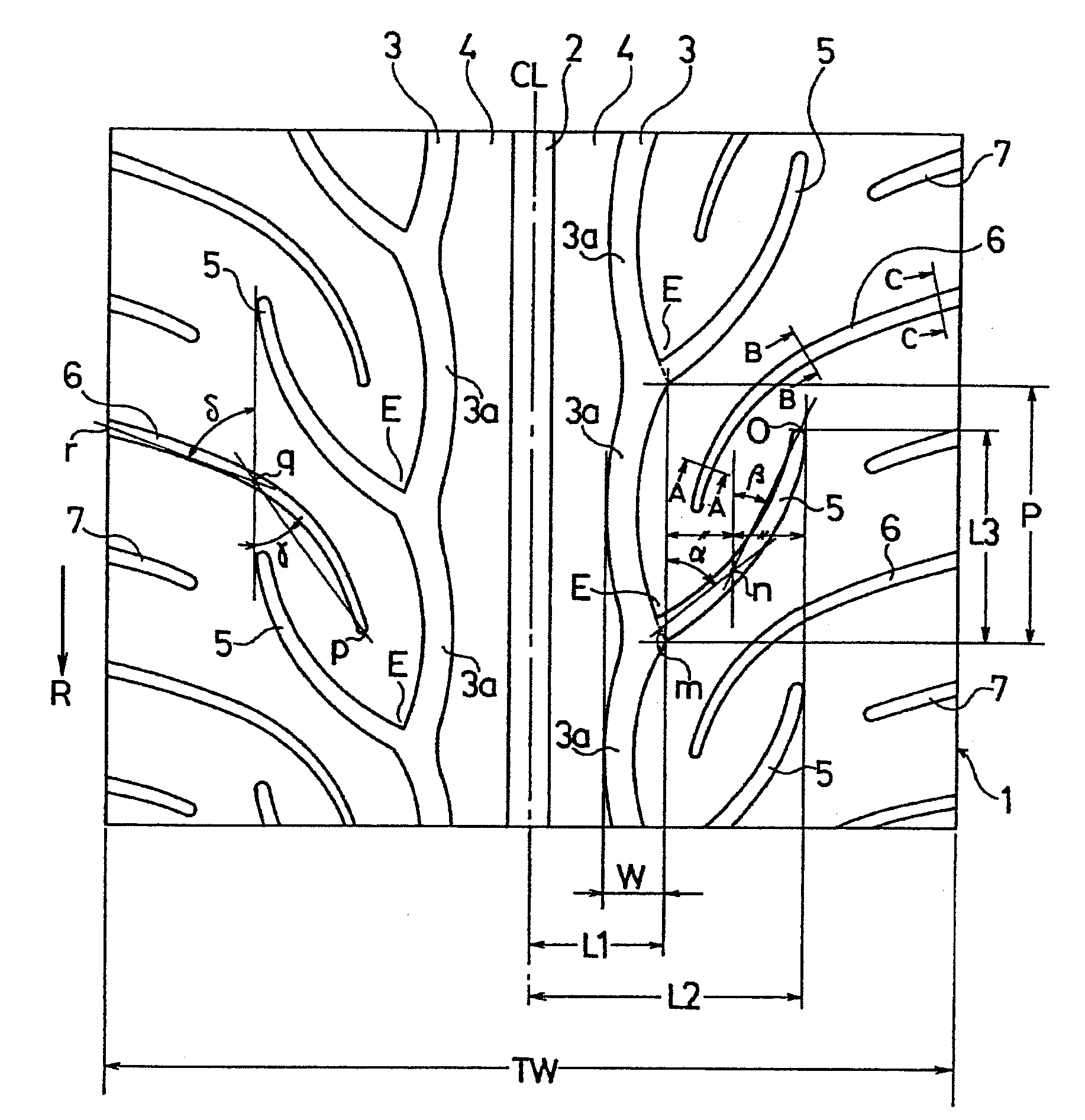
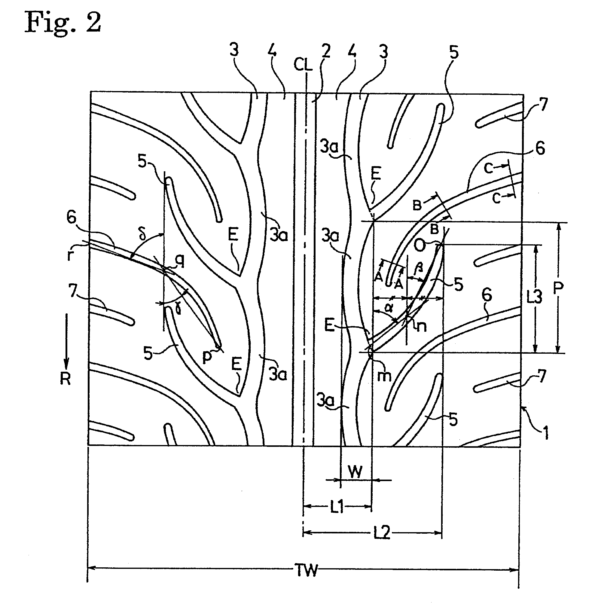
Tread PatternFIG. 2Groove Width of Straight12.7 mmMain Groove 2Groove Width of Wave-shaped9.5 mmMain Groove 3Pitch Length P of Wave-shaped57 mm to 83 mmMain Groove 3 (Arc-shapedGrooves)Number of Pitches of24Wave-shaped Main Groove 3(Arc-shaped Grooves)Groove Width of Diagonal5.0 mmGroove 5Average Oblique Angle α of55°Diagonal Groove 5Average Oblique Angle β of27°Diagonal Groove 5Groove Width of AuxiliaryInner Side in Tire WidthDiagonal Groove 6Directions 2.5 mmOuter Side in Tire WidthDirections 4.0 mmAverage Oblique Angle γ of41°Auxiliary Diagonal Groove 6Average Oblique Angle δ of72°Auxiliary Diagonal Groove 6Groove Width of Auxiliary4.0 mmDiagonal Groove 7

TABLE 1ComparativeExampleExample 1Example 2Tread PatternFIG. 4FIG. 1FIG. 2Driving Stability (Index)100105103Uneven Wear Resistance100103103(Index)Noise Performance (dB)69.769.269.4Drainage Performance10097100(Index)


PUM


Abstract

Disclosed is a pneumatic tire including a straight main groove and two wave-shaped main grooves arranged in the center area of a tread, and diagonal grooves arranged in each shoulder area ranging from each wave-shaped main groove to the outer side of the tire, and extending obliquely outward from the wave-shaped main groove to a direction reverse to the tire rotational direction, the rotational direction being specified for the tire. Each diagonal groove is formed to have a convex protruding toward the outer side of the tire, and the extending end portion of the diagonal groove terminates in the shoulder area. Thus, each shoulder area is provided with a non-block pattern in which a land section continues in the tire circumferential direction. Thereby, the pneumatic tire has increased driving stability and uneven wear resistance while substantially maintaining good drainage performance and noise performance against columnar resonance.

Description

BACKGROUND OF THE INVENTION[0001]1. Field of the Invention[0002]The present invention relates to a pneumatic tire, and specifically to a pneumatic tire which has improved driving stability and uneven wear resistance while maintaining good drainage performance based on main grooves each having a wide groove width and extending in a tire circumferential direction.[0003]2. Description of the Related Art[0004]General measures for improving the drainage performance of a pneumatic tire include a technique of arranging straight main grooves each having a wide groove width respectively in the center area and the two shoulder areas of the tread in the tire circumferential direction. A pneumatic tire with such straight main grooves has improved drainage performance, but suffers from the following problems. First, the straight main grooves cause a large columnar resonance while the tire is being run, and accordingly worsens noise performance. Second, since the straight main grooves each having...

Claims


Application Information

Patent Timeline
IPC IPC(8): B60C11/13
CPCB60C11/0302B60C11/0309B60C11/042B60C2011/0374B60C2011/0369B60C2011/0381B60C11/1323
Inventor YAMANE, KENJI
Owner YOKOHAMA RUBBER CO LTD
Why Eureka
Try Eureka