Connector housing for a small and portable transmitting-receiving module

Active Publication Date: 2009-05-07
NEXTRONICS ENG CORP
View PDF13 Cites 5 Cited by
  • Summary
  • Abstract
  • Description
  • Claims
  • Application Information

AI Technical Summary

Benefits of technology

[0008]One particular aspect of the present invention is to provide a connector housing for a small and portable transmitting-receiving module. The structure strength of the metal housing is enhanced. The metal housing is not easily deformed due to an improper assembling process or an external force. Its structure is simple, and the manufacturing cost is reduced.
[0010]The present invention has the following characteristics. Because the second wedging plate leans against the first wedging plate, the second wedging plate is wedging the two side walls, the first wedging plate is wedging the bottom board, the second convex blocks are plugged into the first indentations and the first convex blocks are plugged into the second indentations, the structure of the connector housing for a small and portable transmitting-receiving module is stronger. The housing is not easily deformed or damaged due to an improper-assembling process or an external force. Its structure is simple, and the manufacturing cost is reduced.

Problems solved by technology

The metal housing is not easily deformed due to an improper assembling process or an external force.

Method used


Image

  • Connector housing for a small and portable transmitting-receiving module
  • Connector housing for a small and portable transmitting-receiving module
  • Connector housing for a small and portable transmitting-receiving module

Examples


Embodiment Construction

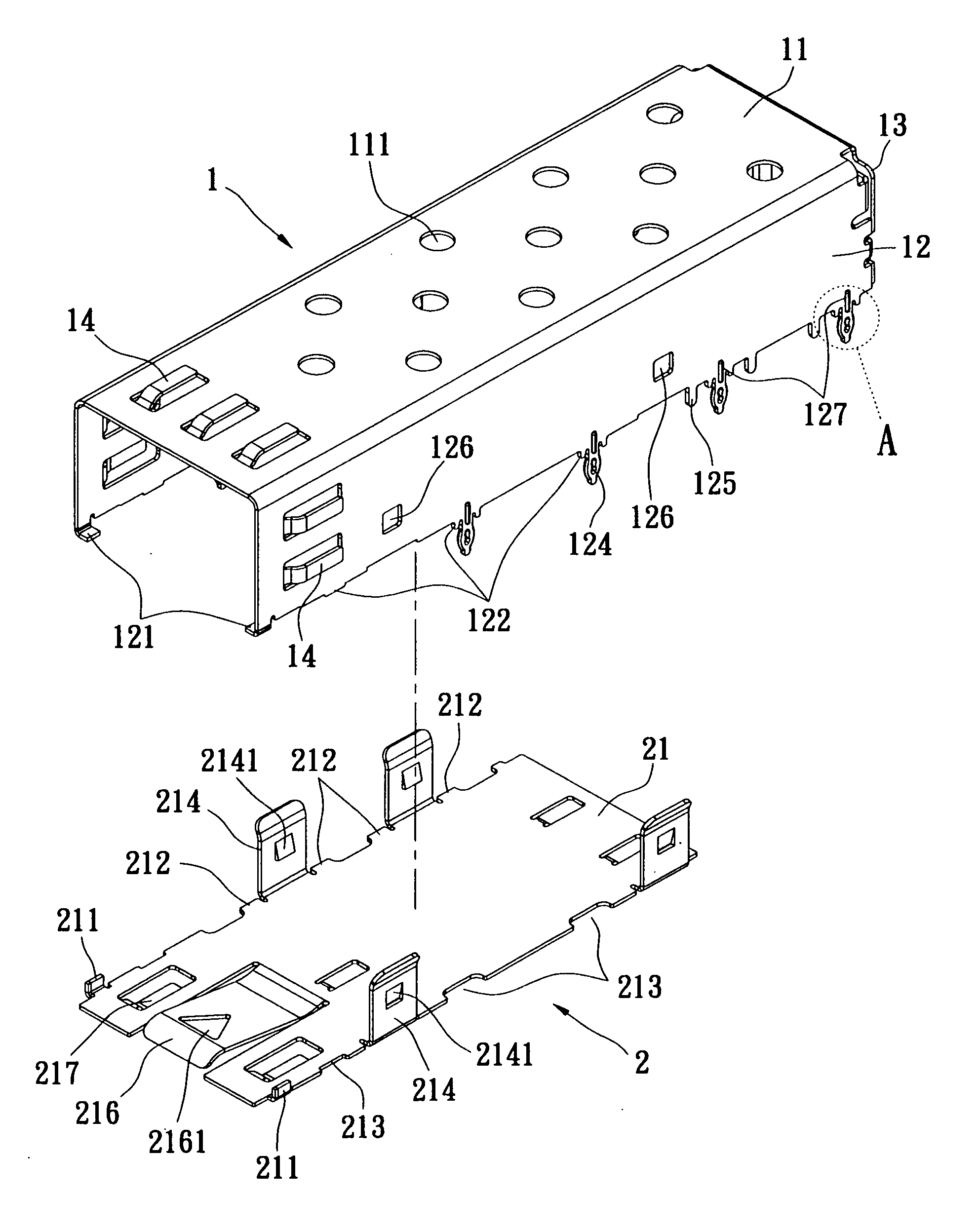
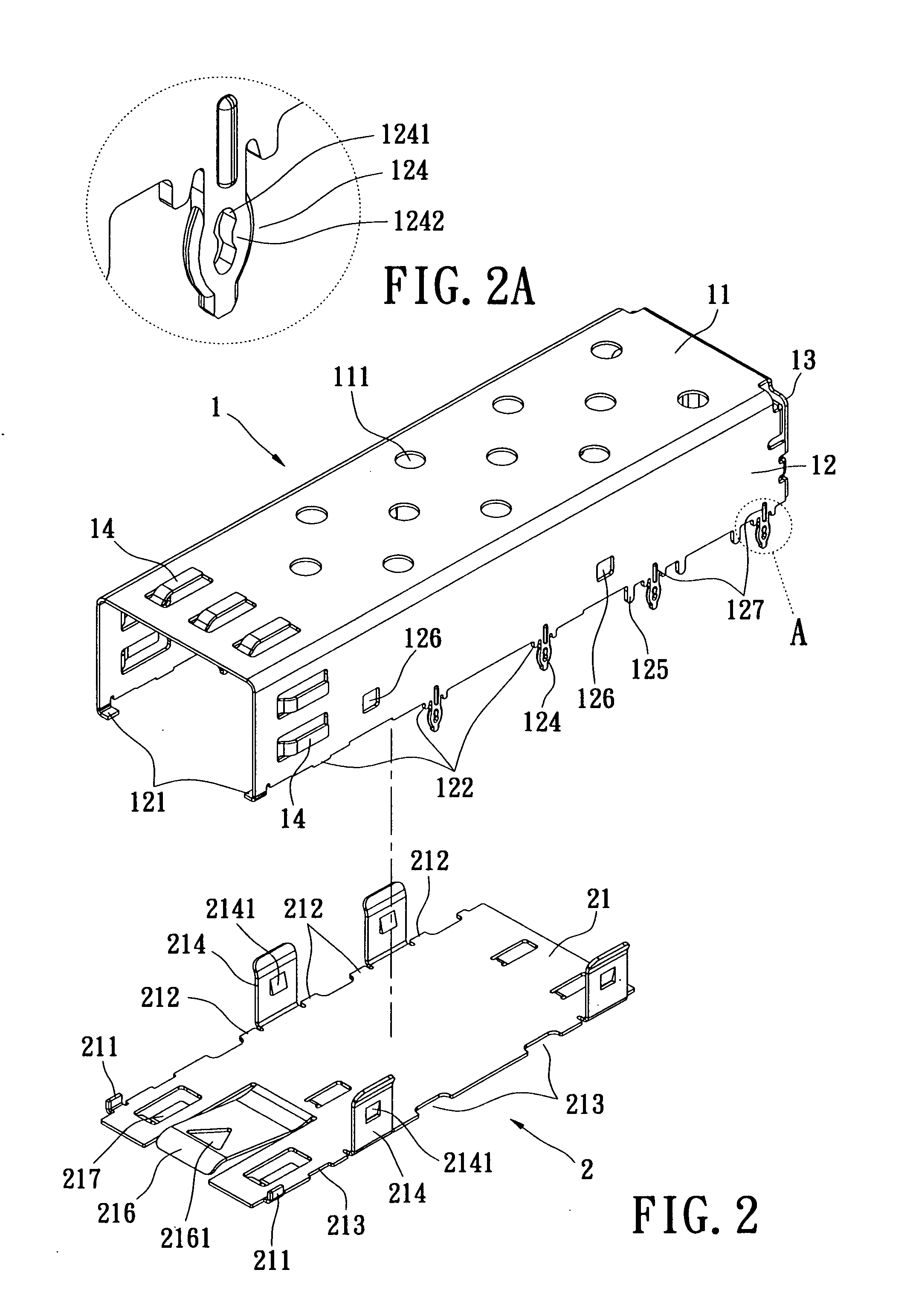
[0020]Reference is made to FIGS. 2-6. The connector housing for a small and portable transmitting-receiving module includes an upper housing 1, and a lower housing 2. The upper housing 1 is formed by bending a single metal board and has an inverted U-shape. The upper housing 1 has a top board 11, two side walls 12, a rear cover 13, and a plurality of first grounding flexible plates 14. The top board 11 is a rectangular metal board and has a plurality of cooling holes 111 for exhausting the heat from the small and portable transmitting-receiving module (not shown in the figure).

[0021]The side wall 12 is a rectangular metal board. The two side walls 12 extend from the two opposite sides of the top board 11. The lower edge of the two side walls 12 has a first wedging plate 121, a plurality of first convex blocks 122, a plurality of first indentations 123, a plurality of needle-hole pins 124, and a plurality of first wedging pins 125. The first wedging plate 121 extends from the front s...


PUM


Abstract

A connector housing for a small and portable transmitting-receiving module includes an upper housing and a lower housing. The upper housing has a top board, two side walls and a rear cover. The lower edge of the two side walls has a first wedging plate, first convex blocks, and first indentations. The lower housing has a bottom board, and the bottom board has a second wedging plate, second convex blocks, and second indentations. The second wedging plate is wedging the two side walls. The first wedging plate is wedging the bottom board. The second convex blocks are plugged into the first indentations. The first convex blocks are plugged into the second indentations. Thereby, the structure of the connector housing is stronger compared to the prior art. The housing is not easily deformed. Its structure is simple, and the manufacturing cost is reduced.

Description

CROSS REFERENCE TO RELATED APPLICATION[0001]This application is a continuation-in-part of U.S. application Ser. No. 11 / 979286, filed on 1 Nov. 2007 and entitled “connector housing for a small and portable transmitting-receiving module”, now pending.BACKGROUND OF THE INVENTION[0002]1. Field of the Invention[0003]The present invention relates to a connector housing for a small and portable transmitting-receiving module. In particular, this invention relates to a connector housing for a small and portable transmitting-receiving module that is used for a high-speed data transmitting interface converter.[0004]2. Description of the Related Art[0005]The transmitting-receiving module provides a dual-directional data transmission between an electric interface and the Internet. The transmitting-receiving module receives an encoded signal, and converts the encoded signal into a decoded signal and transmits the decoded signal to the Internet. At the same time, the transmitting-receiving module ...

Claims


Application Information

Patent Timeline
IPC IPC(8): H01R4/00
CPCH01R12/585H01R13/6594H01R13/502
Inventor SU, HOU-ANWU, CHIN-PAO
Owner NEXTRONICS ENG CORP
Why Eureka
Try Eureka