Sputtering apparatus

a technology of sputtering apparatus and sputtering chamber, which is applied in the direction of vacuum evaporation coating, electrolysis components, coatings, etc., can solve the problems of unbalanced magnetron sputtering process, large ejection of large pieces, and many technological challenges to the equipment, and achieve time-efficient process schedule

Active Publication Date: 2009-05-07
SULZER METAPLAS
View PDF16 Cites 16 Cited by
  • Summary
  • Abstract
  • Description
  • Claims
  • Application Information

AI Technical Summary

Benefits of technology

[0016]It is an object of the current invention to provide an apparatus for coating substrates that allows for a stable and clean mixed mode deposition process. It is a further object of the invention to provide a process that does away with the problem of target contamination in a mixed mode reactor. Another object of the invention is to provide an apparatus and a method that allows for a time-efficient process schedule.

Problems solved by technology

With ‘unbalanced’ is meant that part of the magnetic field lines do not close on the target surface but fan out to the substrate.
Such a process is called ‘unbalanced magnetron sputtering’.
The combination of both processes in one single apparatus poses many technological challenges to the equipment as the requirements of both processes are differing.
Also in the ‘mixed mode’ process wherein sputtering is combined with the administering of an inert and precursor gas (e.g. the sputtering of a Ti target in a acetylene (C2H2)-argon mixture) is difficult to control as a compound layer not only forms on the substrate, but also on the target which leads to undesirable phenomena like arcing (leading to the ejection of larger pieces out of a target) and instability of the process.
Therefore a ‘target contamination’ problem exists in these processes.

Method used


Image

  • Sputtering apparatus
  • Sputtering apparatus
  • Sputtering apparatus

Examples


Embodiment Construction

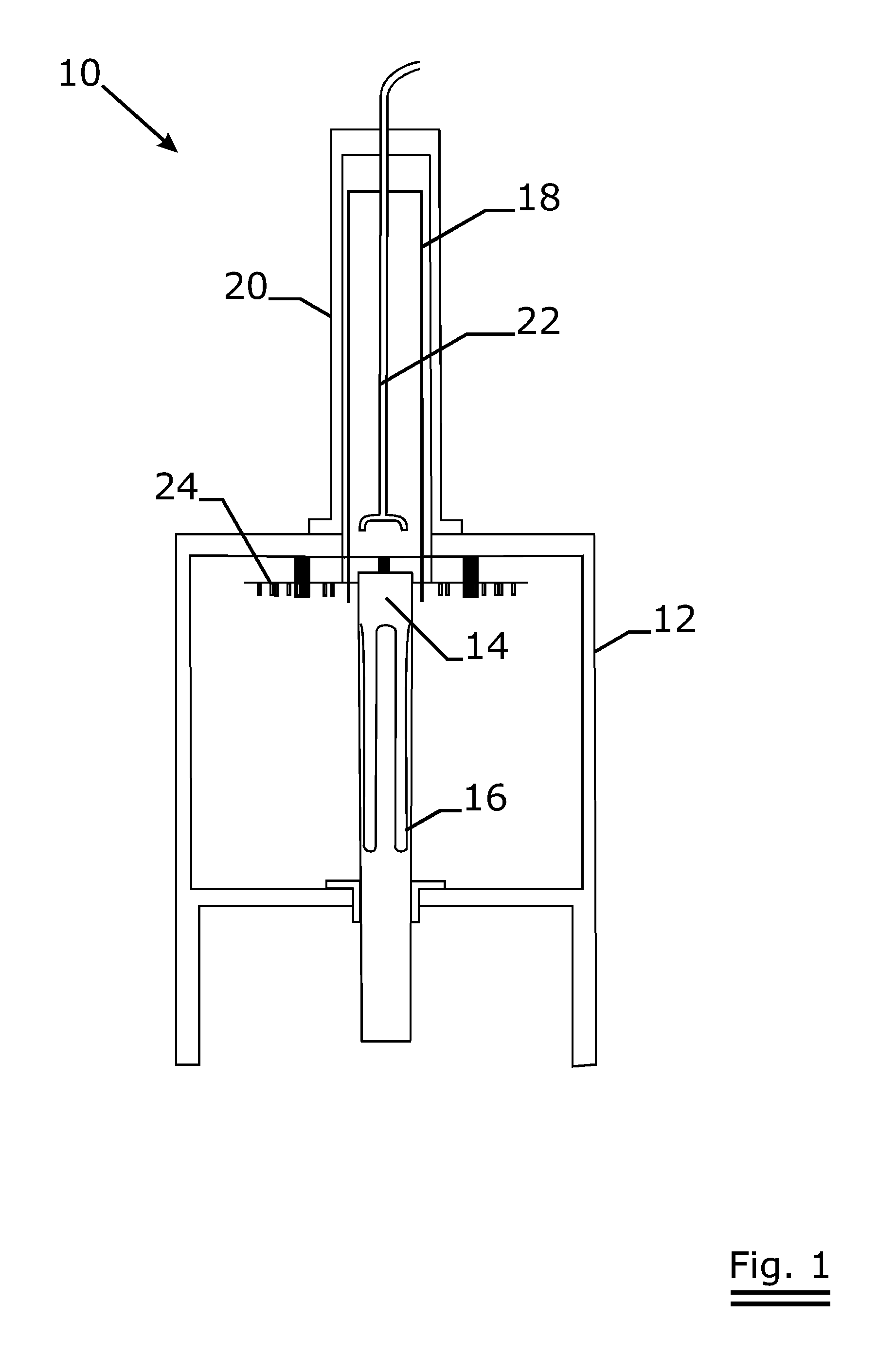
[0056]FIG. 1 shows an overall sketch of the inventive apparatus 10. The apparatus basically consists of an evacuable chamber 12 that for this embodiment is of roughly cubical shape. Inside the chamber 12 a cylindrical target 14 is mounted that in this embodiment is placed centrally and upstanding in the chamber 12. When the apparatus is operative, a sputtering area 16 in the form of a meandering racetrack forms on the surface of the target. On top of the apparatus a hat-shaped housing 20 is mounted vacuum tight to the chamber 12. Inside the housing 20 a cylindrical shutter 18 can be moved up and down. When retracted, the shutter uncovers the sputtering area 16. When extended—in this embodiment obtained by lowering the shutter 18—the shutter covers the sputtering area 16. Inside the housing a gas distribution system in the form of a tree 22 is present that feeds processing gas in the gap between the shutter 18 and the target 14. Around the target 14 and the shutter 18 a planetary sub...


PUM

PropertyMeasurementUnit
pressuresaaaaaaaaaa
pressuresaaaaaaaaaa
pressuresaaaaaaaaaa

Abstract

A coating apparatus is revealed that is designed to coat substrates by means of a physical vacuum deposition process or a chemical vacuum deposition process or a combination thereof. Said coating apparatus is particular in that it uses a rotatable magnetron (14) that is coverable with an axially moveable shutter (18). Such an arrangement enables to keep the magnetron target clean or to clean the target in between or even during subsequent coating steps. The shutter further provides for a controllable gas atmosphere in the vicinity of the target. The arrangement wherein the magnetron is centrally placed is described. Substrates are then exposed to the sputtering source from all angles by hanging them on a planetary carousel (24) that turns around the magnetron.

Description

FIELD OF THE INVENTION[0001]The invention relates to a coating apparatus that uses a rotatable target as a sputter material source. The coating apparatus is equipped with a tubular shutter that can be axially extended over or axially retracted from the sputter zone of the target. The apparatus is particularly intended for mixed mode coating processes in which physical vapour deposition (PVD) processes alternate with chemical vapour deposition (CVD) processes or are effected simultaneously.BACKGROUND OF THE INVENTION[0002]In the art of deposition of optically, electrically, chemically, magnetically or mechanically functional coatings, the physical vapour deposition (PVD) and the chemical vapour deposition (CVD) prevail. Physical vapour deposition relates to processes wherein the coating is built-up by a ballistic shower of the substrate with coating atoms. The coating atoms originate from a usually solid, sometimes liquid ‘target’. A preferred way of transferring the target species t...

Claims


Application Information

Patent Timeline
Patent Type & Authority Applications(United States)
IPC IPC(8): C23C14/34
CPCC23C14/34H01J37/3447H01J37/3405C23C14/56
Inventor DEKEMPENEER, ERIKDE BOSSCHER, WILMERTVERHEYEN, PASCAL
Owner SULZER METAPLAS
Why Eureka
Try Eureka