Piezoelectric loudspeaker

a piezoelectric and loudspeaker technology, applied in piezoelectric/electrostrictive/magnetostrictive devices, piezoelectric/electrostriction/magnetostriction machines, electrical transducers, etc., can solve the problems of poor speaker peaks or dips are more prone to peaks or dips in frequency response, and the sound quality of piezoelectric speakers is typically limited. , the effect o

Inactive Publication Date: 2009-05-07
VIBRATION X
View PDF6 Cites 4 Cited by
  • Summary
  • Abstract
  • Description
  • Claims
  • Application Information

AI Technical Summary

Benefits of technology

[0015]Another object is to design a simple and inexpensive piezoelectri

Problems solved by technology

Conventional wisdom says that speakers driven within their break up region have poor quality sound because the resulting resonances create audible peaks and dips in the frequency response.
These speakers also are more prone to peaks or dips in the frequency response in the crossover region where two transducers may be operating at the same output level.
The sound quality of a piezoelectric speaker is typically limited by the shape and size of the structure to which the piezoelectric material is attached.
For this reason, prior use of piezoelectric materials used to generate audio soun

Method used


Image

  • Piezoelectric loudspeaker
  • Piezoelectric loudspeaker
  • Piezoelectric loudspeaker

Examples


Embodiment Construction

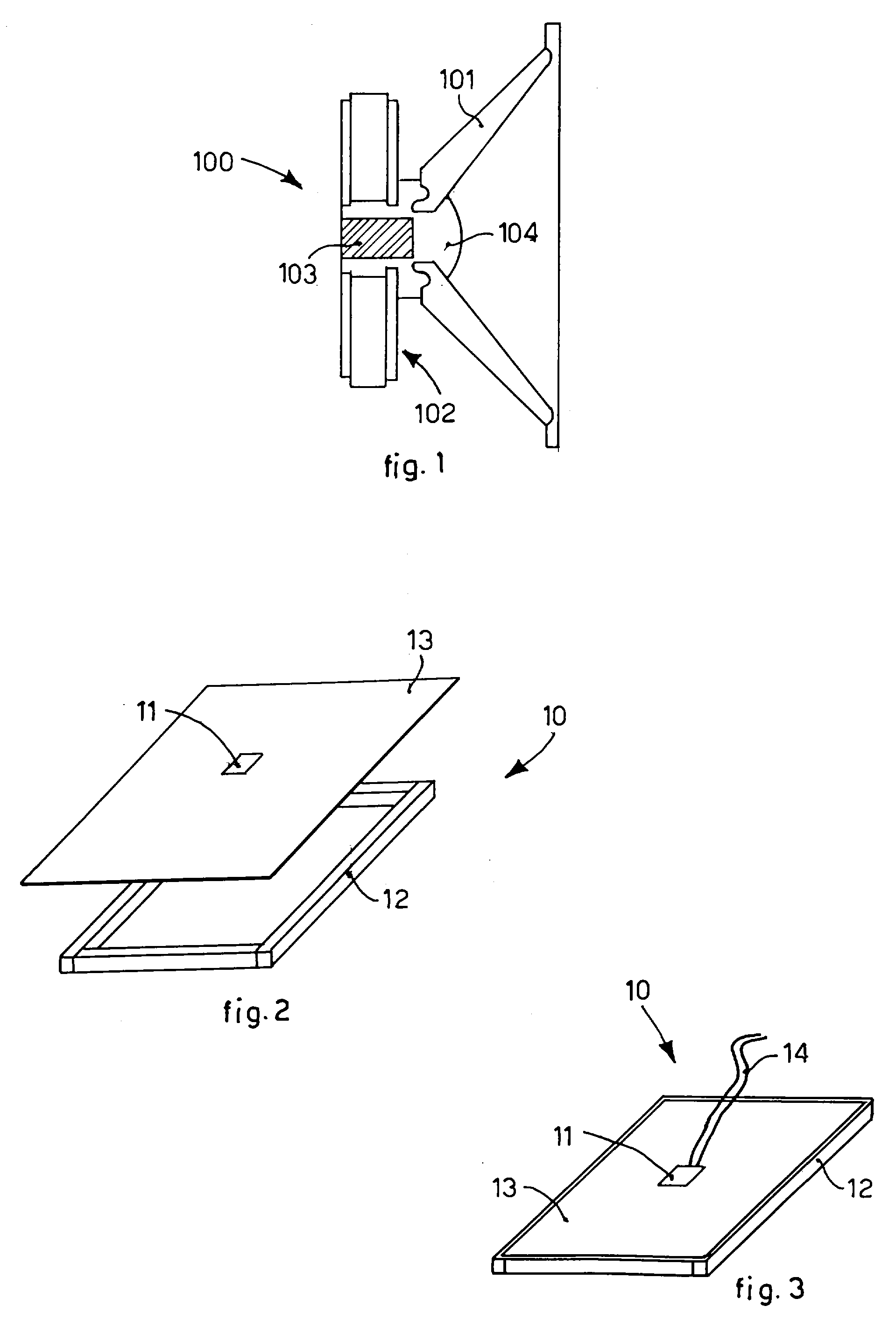
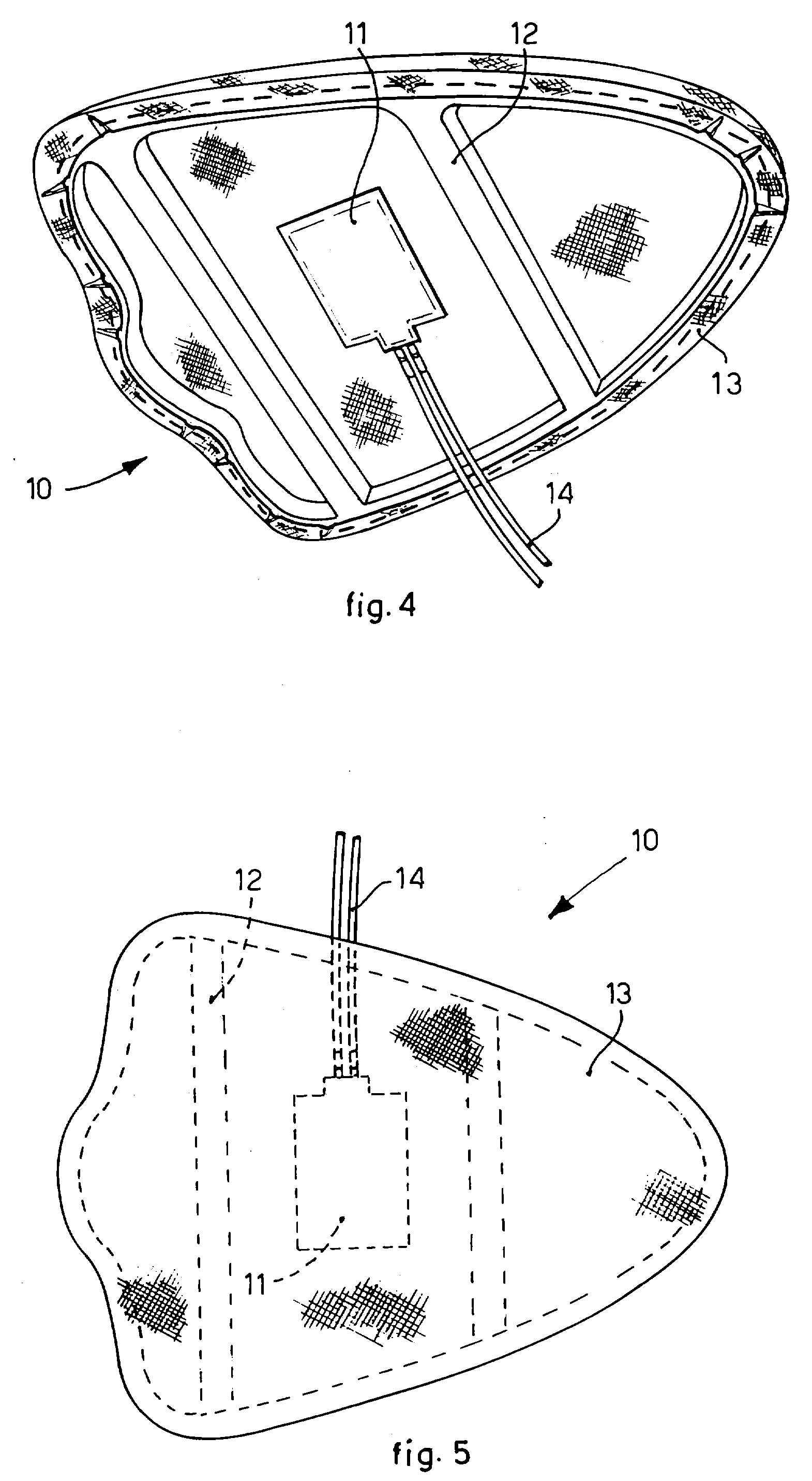
[0054]The piezoelectric loudspeaker 10 according to the invention is shown in a form of embodiment in FIGS. 4 and 5.

[0055]In this form of embodiment, the loudspeaker 10 includes a single small piezoelectric actuator 11, but it is clear that it could as well include a multiplicity of piezoelectric actuators distributed on the surface of the panel. The number and the distribution of the piezoelectric actuators 11 on the surface of the loudspeaker 10 may be designed according to the specific application and the audio performance to be obtained.

[0056]The loudspeaker 10 comprises, as its essential components, a thin frame 12 (see step 20 in the block diagram of FIG. 6) which can have a suitable shape according to the needed requirements for the installation. In addition, the frame member may comprise any opening formed in a solid structure that the fabric membrane can be stretched across. One example is an opening formed in an automobile dashboard or door panel. Another example is an ope...


PUM

PropertyMeasurementUnit
Frequencyaaaaaaaaaa
Frequencyaaaaaaaaaa
Frequencyaaaaaaaaaa

Abstract

A full range loudspeaker, comprising a frame with a membrane secured onto said frame and a piezoelectric actuator attached on said membrane and able to be driven over the full audible frequency range.

Description

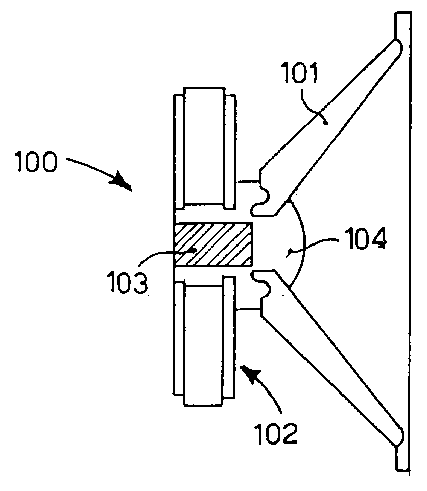
[0001]The present invention refers to a piezoelectric loudspeaker, and to a method to design and make a full range piezoelectric loudspeaker. More particularly, the piezoelectric loudspeaker according to the invention has an improved low frequency response, and is able to be driven at a wide range of audio signal frequencies, e.g. from about 5 Hz up to 100 KHz.STATE OF THE ART[0002]Piezoelectric loudspeakers have been used in audio systems to generate high frequency audio sound (tweeters, ultrasonic sound generators, etc.), but they have never been used to cover the low frequency range, which is typically covered by a conventional voice coil speaker.[0003]Sound system designers historically have used electromagnetic “voice coil” transducers to generate air displacement.[0004]FIG. 1 discloses an embodiment of a prior art “voice coil” transducer 100. The transducer 100 consists of a suspended cone 101 that is pushed in and out by an attached voice coil 104, which moves through a magne...

Claims


Application Information

Patent Timeline
IPC IPC(8): H01L41/00H04R31/00
CPCY10T29/49005H04R17/00
Inventor BIANCHINI, EMANUELE
Owner VIBRATION X
Why Eureka
Try Eureka