Faulted circuit indicator apparatus with transmission line state display and method of use thereof

a technology of state display and capacitor, which is applied in the direction of line-transmission details, line-transmission monitoring/testing, instruments, etc., can solve the problems of inability to safely rely solely on fault indication from prior art fci, inability to locate transient or intermittent faults, and inability to safely rely on prior art fci fault indications

Active Publication Date: 2009-05-07
EATON INTELLIGENT POWER LIMITED
View PDF71 Cites 54 Cited by
  • Summary
  • Abstract
  • Description
  • Claims
  • Application Information

AI Technical Summary

Benefits of technology

[0011]The present invention satisfies the above-described needs by providing a faulted circuit indicator that has an indicator for indicating both the occurrence of a fault event as well as the state of an electrical conductor. The faulted circuit indicator includes a sensor for collecting data relating to the state of a

Problems solved by technology

Simply turning off a single feed circuit to a particular portion of a transmission line may not guarantee that a particular line is de-energized.
Furthermore, in some three-phase power systems, one phase may fault and trip an FCI, while the other phases remain energized.
Thus, technicians must carry additional equipment to determine whether a particular transmission line is de-energized, and cannot safely rely solely on a fault indication from a prior art FCI.
Further, because of their binary nature, prior art FCIs provide little assistance in locating a transient or intermittent fault.
The result of an automatic reset is, however, that an intermittent or transient fault would trigger an FCI's indicator only for a short time, followed by an immediate reset of the indicator, making the location of a faulted FCI during the presence of a faulted condition nearly impossible.
Moreover, prior art FCIs cannot monitor other conditions on a transmission line that may pose risks to the life or performance of the transmission line and other related equipment.
For example, power surges at certain levels may not be sufficient to result in a fault condition that would be indicated by present FCIs, but may shorten the life of a transm

Method used


Image

  • Faulted circuit indicator apparatus with transmission line state display and method of use thereof
  • Faulted circuit indicator apparatus with transmission line state display and method of use thereof
  • Faulted circuit indicator apparatus with transmission line state display and method of use thereof

Examples


Embodiment Construction

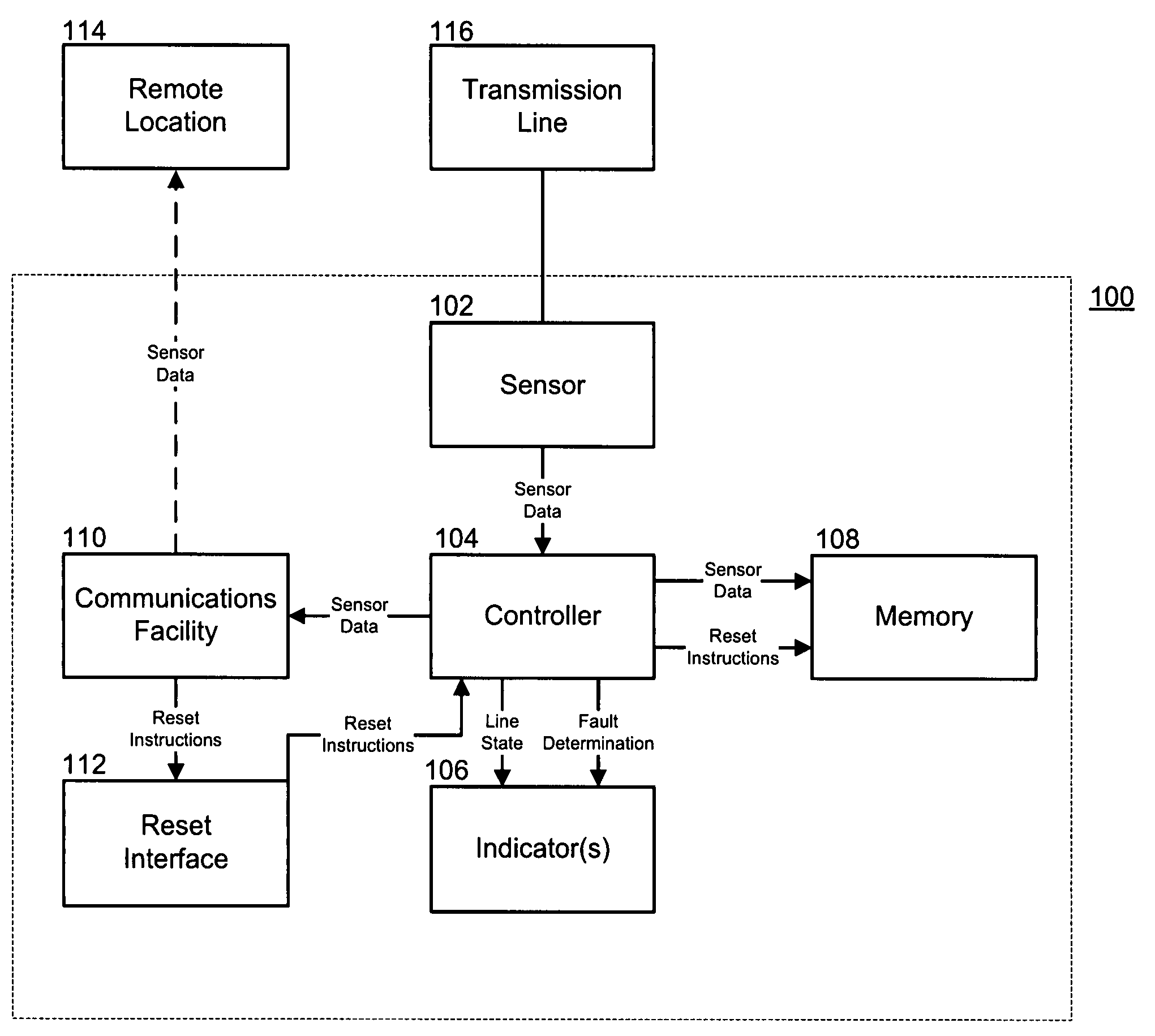
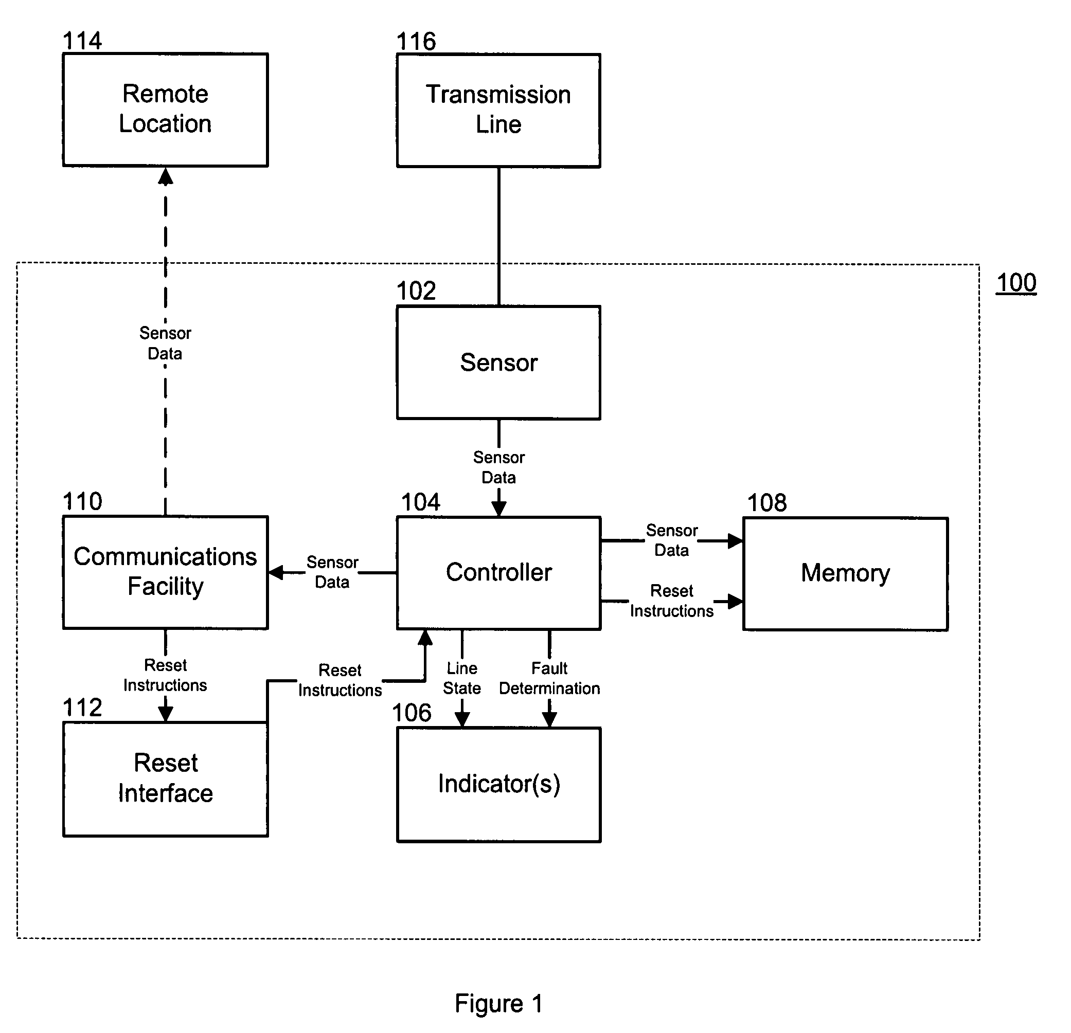
[0020]The present invention provides a faulted circuit indicator (FCI) system capable of determining the state of a transmission line with respect to a variety of characteristics, storing the state information, and communicating the state information by means of an indicator attached to the FCI, by transmission of the information to a remote location, or both. Prior art FCIs are not capable of displaying the present state of a transmission line, nor are prior art FCIs capable of transmitting fault information and present state information relating to a transmission line to a remote location.

[0021]The FCI system is constantly attached to a transmission line, which allows electric utility companies to increase safety for line technicians, and improve their ability to diagnose and repair problems within a distribution system. The display of state information notifies a technician whether a line is energized without necessitating close contact with a transmission line. The constant moni...


PUM

PropertyMeasurementUnit
Temperatureaaaaaaaaaa
Currentaaaaaaaaaa
Electrical conductoraaaaaaaaaa

Abstract

The invention provides a faulted circuit indicator apparatus with transmission line state display, as well as methods for using the apparatus. The faulted circuit indicator has a sensor that can be electrically coupled to an electrical conductor for collecting data relating to a state of the electrical conductor. The faulted circuit indicator also has a controller that is logically coupled to the sensor for receiving data and determining whether a fault condition has occurred on the electrical conductor. The faulted circuit indicator also has one or more indicators that are logically coupled to the controller for indicating whether a fault condition has occurred as well as the state of the electrical conductor. The state of the conductor may be the voltage, the temperature, or the vibration present on the conductor.

Description

RELATED APPLICATIONS[0001]This application is related to U.S. patent application Ser. No. ______, [Attorney Docket No. 13682.105186] entitled “Communicating Faulted Circuit Indicator Apparatus and Method of Use Thereof,” filed on Nov. 2, 2007.TECHNICAL FIELD[0002]The present invention relates generally to faulted circuit indicators and more particularly to the communication of the state of a transmission line, including real-time or near real-time measurements of electrical current and voltage, as well as other present-state information, by the faulted circuit indicator.BACKGROUND OF THE INVENTION[0003]Faulted circuit indicators (FCIs) are well known in the field of electric power distribution systems. Generally, FCIs are electrically connected to transmission lines in a power distribution system at various locations throughout the system, often in close proximity to system loads. When a fault occurs in a transmission line, FCIs between the power source and the fault will detect tha...

Claims


Application Information

Patent Timeline
IPC IPC(8): G01R31/02H02G1/00
CPCY10T29/49718G01R19/2513
Inventor MUENCH, JR., FRANK JOHNBANTING, JOHN FREDRICK
Owner EATON INTELLIGENT POWER LIMITED
Why Eureka
Try Eureka