Image-pickup apparatus and control method for image-pickup apparatus

Inactive Publication Date: 2009-05-07
CANON KK
View PDF18 Cites 67 Cited by
  • Summary
  • Abstract
  • Description
  • Claims
  • Application Information

AI Technical Summary

Benefits of technology

[0020]The present invention provides an image-pickup apparatus capable of performing focus control with a highly accurate contrast detection method by increasing re

Problems solved by technology

When performing focus control with the contrast detection method as in the image-pickup apparatus disclosed in Japanese Patent Laid Open No. 2001-305415, contrast evaluation may be inaccurate if noise contaminates a brightness signal obtained by photoelectric conversion o

Method used


Image

  • Image-pickup apparatus and control method for image-pickup apparatus
  • Image-pickup apparatus and control method for image-pickup apparatus
  • Image-pickup apparatus and control method for image-pickup apparatus

Examples


Example

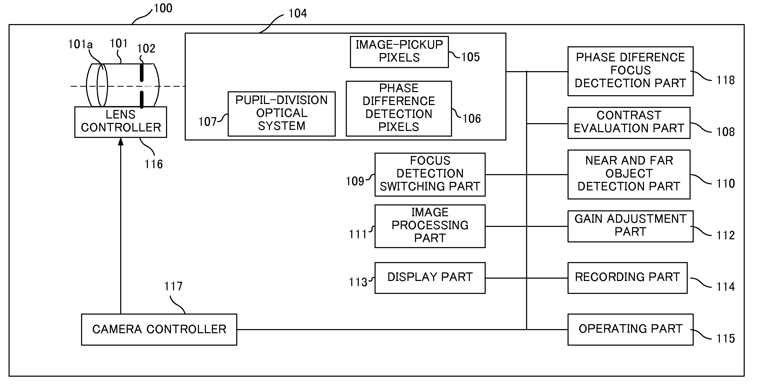
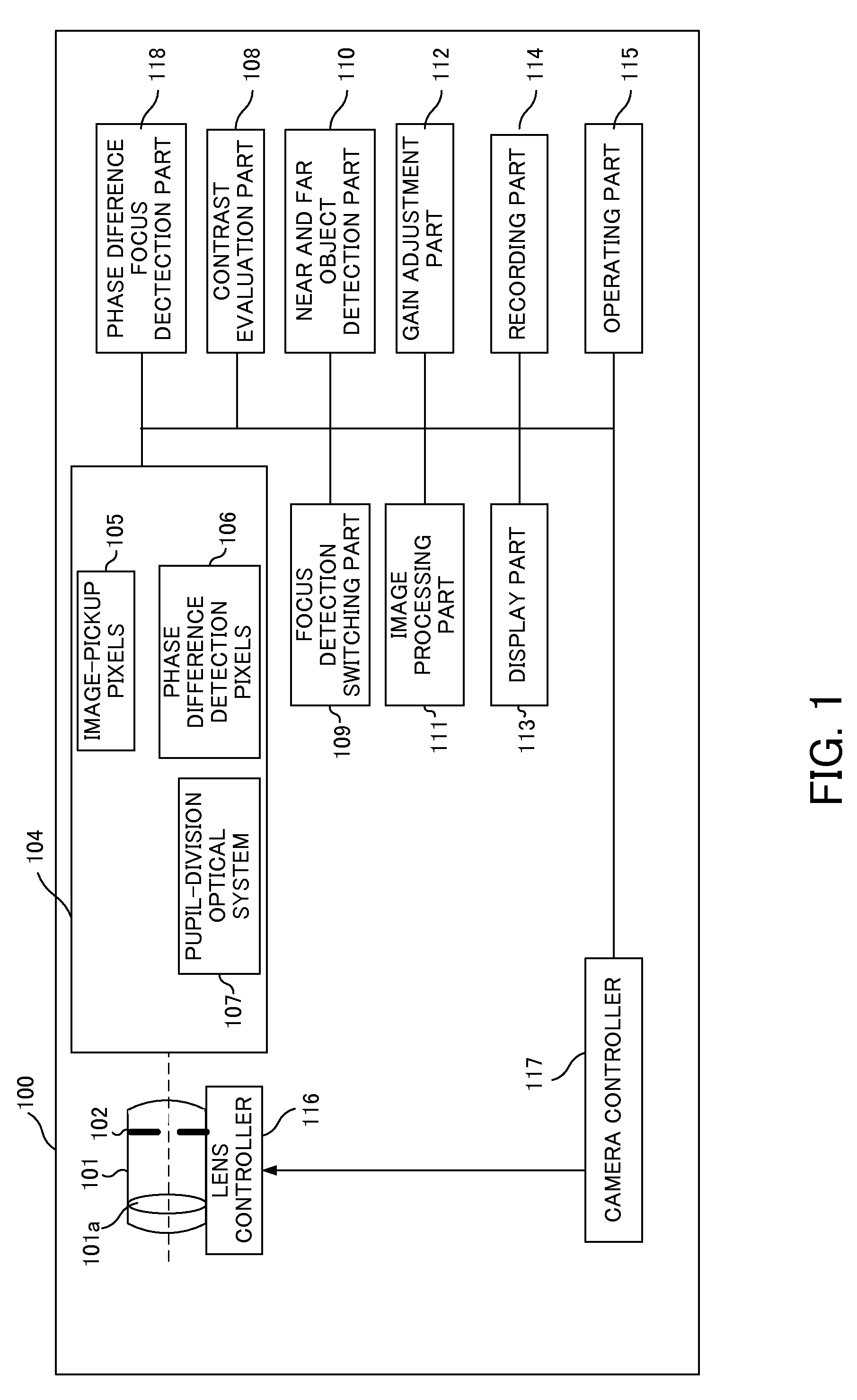
[0041]FIG. 1 shows the configuration of a digital still camera as an image-pickup apparatus that is a first embodiment (Embodiment 1) of the present invention.

[0042]The camera 100 includes an image-pickup optical system 101 that forms an object image of an object with a light flux, a lens controller 116 that controls the position of a focus lens 101a included in the image-pickup optical system 101, and an aperture stop 102 that adjusts the amount of light passing through the image-pickup system 101. The camera 100 also includes an image-pickup element 104 as a photoelectric conversion element, which is constituted by a CMOS sensor. The object image formed by the light flux from the image-pickup optical system 101 is formed on a light-receiving surface of the image-pickup element 104.

[0043]The image-pickup element 104 includes a group of image-pickup pixels (first type pixels) 105 constituted by plural image-pickup pixels for photoelectrically converting the object image formed by th...

Example

Embodiment 2

[0095]In Embodiment 1, the contrast evaluation area is changed such that it includes only the phase difference focus detection areas for which the phase difference in-focus positions are located at the closer distance side among the phase difference focus detection areas included in the original contrast evaluation area. Further, the range (minute scanning range) within which the focus lens 101a is moved for the contrast evaluation in the changed contrast evaluation area is set to a range near (including) the phase difference in-focus position located closest to the close distance end.

[0096]In contrast, in the present embodiment, the focus lens 101a is moved in ranges (minute scanning ranges) near (including) the phase difference in-focus positions of the plural phase difference focus detection areas included in the contrast evaluation area which is the original contrast evaluation area or the changed contrast evaluation area described in Embodiment 1. Thereby, the cont...


PUM


Abstract

The image-pickup apparatus includes an image-pickup element including first type pixels photoelectrically converting an object image formed by a light flux from an optical system and second type pixels photoelectrically converting plural images formed by plural light fluxes divided from the light flux from the optical system, a controller performing contrast detection focus control using signals from pixels in a contrast evaluation area among the first type pixels, and a detector detecting phase differences of respective pairs of images of the plural images using signals from the second type pixels, the pairs of images being respectively formed in plural phase difference detection areas in the contrast evaluation area, and calculating information on an in-focus position of the optical system or object distance for each phase difference detection area based on each phase difference. The controller changes the contrast evaluation area based on the information calculated for the respective phase difference detection areas.

Description

BACKGROUND OF THE INVENTION[0001]The present invention is related to an image-pickup apparatus such as a digital still camera or a video camera, and is specifically related to an image-pickup apparatus which uses image-pickup pixels and focus detection pixels in an image-pickup element to perform focus control with a contrast detection method.[0002]Japanese Patent Laid-Open No. 2000-156823 discloses an image-pickup apparatus, in which some pixels (focus detection pixels) included in an image-pickup element used in the apparatus are provided with different optical characteristics from those of other pixels to perform focus detection based on outputs from the focus detection pixels.[0003]In the image-pickup apparatus disclosed in Japanese Patent Laid-Open No. 2000-156823, plural focus detection pixels paired with each other are arranged in part of the image-pickup element. FIG. 9 shows one example of a pixel arrangement of the image-pickup element in which the focus detection pixels a...

Claims


Application Information

Patent Timeline
IPC IPC(8): H04N5/225H04N5/232
CPCG03B7/28H04N5/23212G03B13/36H04N23/672H04N23/673H04N25/704H04N25/134
Inventor KAWARADA, MASAHIRO
Owner CANON KK
Why Eureka
Try Eureka