Display panel and display device

a display panel and display panel technology, applied in non-linear optics, instruments, optics, etc., can solve the problems of difficult to display an image with uniform display quality, hardly disclose the shape of the display region, and the like of the display region, and achieve the effect of effectively suppressing the light leakage generated near the shielding member

Active Publication Date: 2009-05-07
UNIFIED INNOVATIVE TECH
View PDF9 Cites 85 Cited by
  • Summary
  • Abstract
  • Description
  • Claims
  • Application Information

AI Technical Summary

Benefits of technology

[0031]Among these, a black mask is particularly preferable as the above-mentioned shielding member. If a black mask is used as the shielding member, the shielding member can be arranged closer to the light-emitting or light-dimming portion of the display panel. Therefore, light leakage generated near the shielding member can be effectively suppressed.
[0032]A plurality of members may be combined to be used as the above-mentioned shielding member. It is preferable that the shielding member specifies the contour of the display region from the viewpoint that the display panel and the display device according to a preferred embodiment of the present invention are easily realized.

Problems solved by technology

However, these documents hardly disclose a shape, an embodiment, and the like of components in the display region.
Therefore, it becomes difficult to display an image with uniform display quality in the display region.

Method used


Image

  • Display panel and display device
  • Display panel and display device
  • Display panel and display device

Examples


embodiment 1

Preferred Embodiment 1

[0048]Preferred Embodiment 1 of the present invention is described with reference to FIGS. 1 to 3. According to the present preferred embodiment, a liquid crystal display panel is exemplified as the display panel and a liquid crystal display device is exemplified as the display device. However, the display panel and the display device of the present invention are not especially limited as long as they are flat panel displays. In addition to the liquid crystal display panel and the liquid crystal display device, a PDP, a plasma display device, an organic EL display panel, an organic EL display device, a field emission display panel, a field emission display device, and the like may be used.

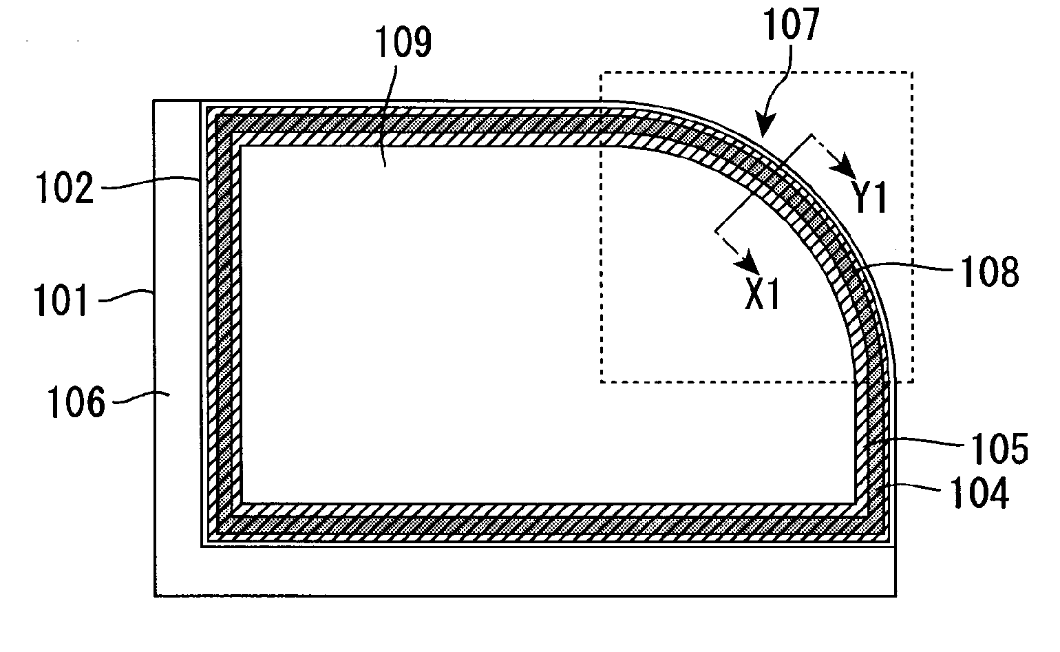
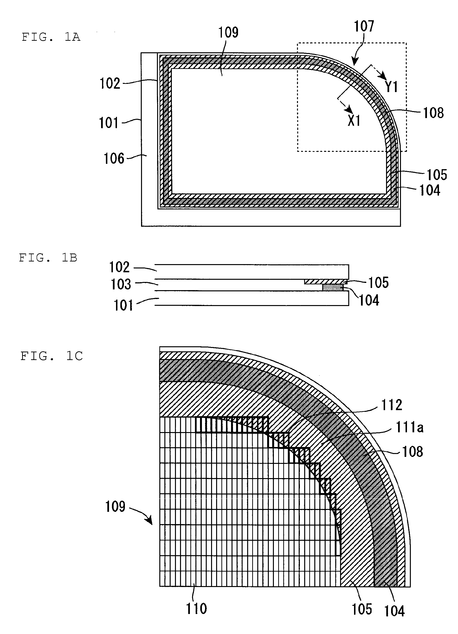
[0049]FIG. 1A is a schematic front view showing a display panel in accordance with the present preferred embodiment. FIG. 1B is a schematic cross-sectional view taken along line X1-Y1 in FIG. 1A. FIG. 1C is an enlarged planar view schematically showing a region surrounded by t...

embodiment 2

Preferred Embodiment 2

[0083]Preferred Embodiment 2 of the present invention is described with reference to FIG. 4.

[0084]FIG. 4 is a schematic front view showing a display panel in accordance with preferred embodiment. The explanation for the same contents as in Preferred Embodiment 1 is omitted in Preferred Embodiment 2.

[0085]According to the present preferred embodiment, the first substrate 201 and the second substrate 202 (a pair of substrates) each have a plurality of substrate curved portions 207, as shown FIG. 4. The light-shielding member (in FIG. 4, a region shown by the upward-sloping line) includes a plurality of shielding curved portions along the substrate curved portions 207 of the first substrate 201 and the second substrate 202. Further, the pixels (not shown) include pseudo curved pixels in a plurality of regions along the plurality of shielding curved portions. As a result, the contours of the display region and the display device can be more freely designed.

[0086]In...

embodiment 3

Preferred Embodiment 3

[0087]The present invention is described with reference to Preferred Embodiment 3 of the present invention with reference to FIG. 5.

[0088]FIG. 5 is a schematic front view showing a display panel in accordance with the present Embodiment. FIGS. 6A to 6D are enlarged planar views showing the regions a, b, c, and d surrounded by the broken lines, in FIG. 5, respectively. The explanation for the same contents as in Preferred Embodiments 1 and 2 is omitted in Preferred Embodiment 3.

[0089]In the display panel according to a preferred embodiment of the present invention, the shielding member is not necessarily arranged along the contours of the substrates. Accordingly, the display panel of the present invention may have an embodiment in which a shielding member 305a is arranged not to correspond to the contours of the first substrate 301 and the second substrate 302 that are a pair of substrates, as shown in FIG. 5.

[0090]According to the shielding member 305a of the p...


PUM

PropertyMeasurementUnit
planar shapeaaaaaaaaaa
shapeaaaaaaaaaa
circumferenceaaaaaaaaaa

Abstract

Each of a display panel and a display device includes a display region in which an image with uniform display quality is displayed and a curved line can be displayed in the contour. The display panel includes a shielding member and a plurality of pixels arrayed in a display region, wherein the shielding member includes a shielding curved portion having a curved planar shape, and the shielding curved portion shields the plurality of pixels to form a curved contour of the display region.

Description

BACKGROUND OF THE INVENTION[0001]1. Field of the Invention[0002]The present invention relates to a display panel and a display device. More specifically, the present invention relates to a display panel and a display device, preferably used in a flat panel display such as an in-car instrumental panel, a car navigation system, a display device for amusement equipment.[0003]2. Description of the Related Art[0004]Flat panel displays (hereinafter, also referred to as a “FPD”) which can be reduced in thickness or increased in size have been widely spread as a display device such as a TV and a display for personal computers. A liquid crystal display device, a plasma display device and the like may be mentioned as a FPD which has been practically used, currently.[0005]According to a common liquid crystal display device, alignment of liquid crystals interposed between a pair of substrates is electrically controlled, and thereby an amount of light passing through the substrates from a backli...

Claims


Application Information

Patent Timeline
Patent Type & Authority Applications(United States)
IPC IPC(8): G02F1/1333
CPCG02F1/133512G02F1/134309G02F1/133606G02F2201/56
Inventor MIMURA, YASUHIRO
Owner UNIFIED INNOVATIVE TECH
Why Eureka
Try Eureka