Illumination apparatus, illumination method, exposure apparatus, and device manufacturing method

a technology of illumination apparatus and exposure apparatus, which is applied in the field of illumination apparatus, exposure apparatus, and device manufacturing method, can solve the problem of not obtaining a multi-level pupil luminance distribution

Active Publication Date: 2009-05-07
NIKON CORP
View PDF94 Cites 174 Cited by
  • Summary
  • Abstract
  • Description
  • Claims
  • Application Information

AI Technical Summary

Problems solved by technology

Since the technology in the above-cited Document 2 uses the spatial filter to obtain the multilevel pupil luminance distribution, it fails to obtain a multilevel pupil luminance distribution in which luminances (light intensities) in respective zones on the illumination pupil plane are optionally controlled.

Method used


Image

  • Illumination apparatus, illumination method, exposure apparatus, and device manufacturing method
  • Illumination apparatus, illumination method, exposure apparatus, and device manufacturing method
  • Illumination apparatus, illumination method, exposure apparatus, and device manufacturing method

Examples


Embodiment Construction

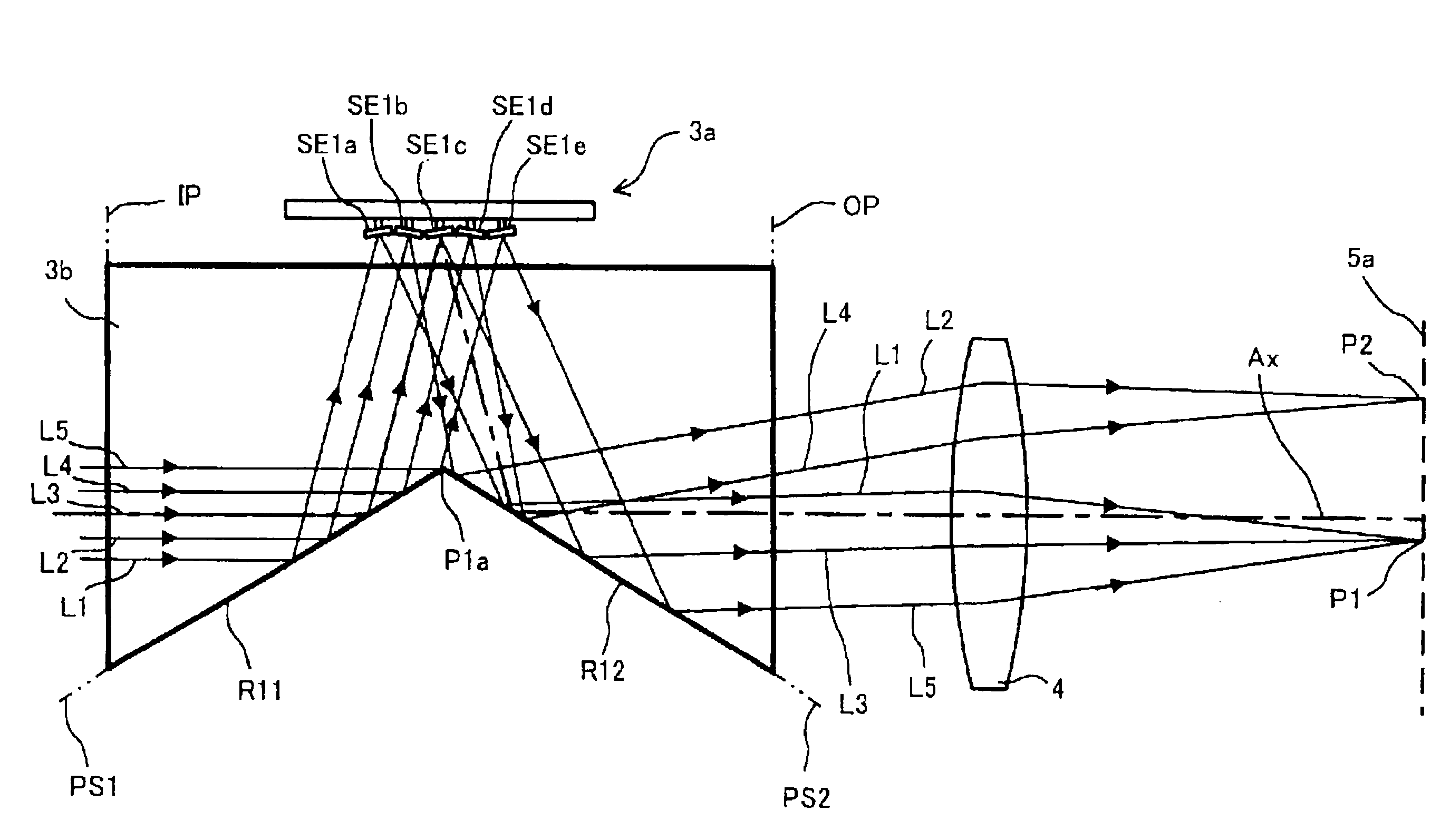
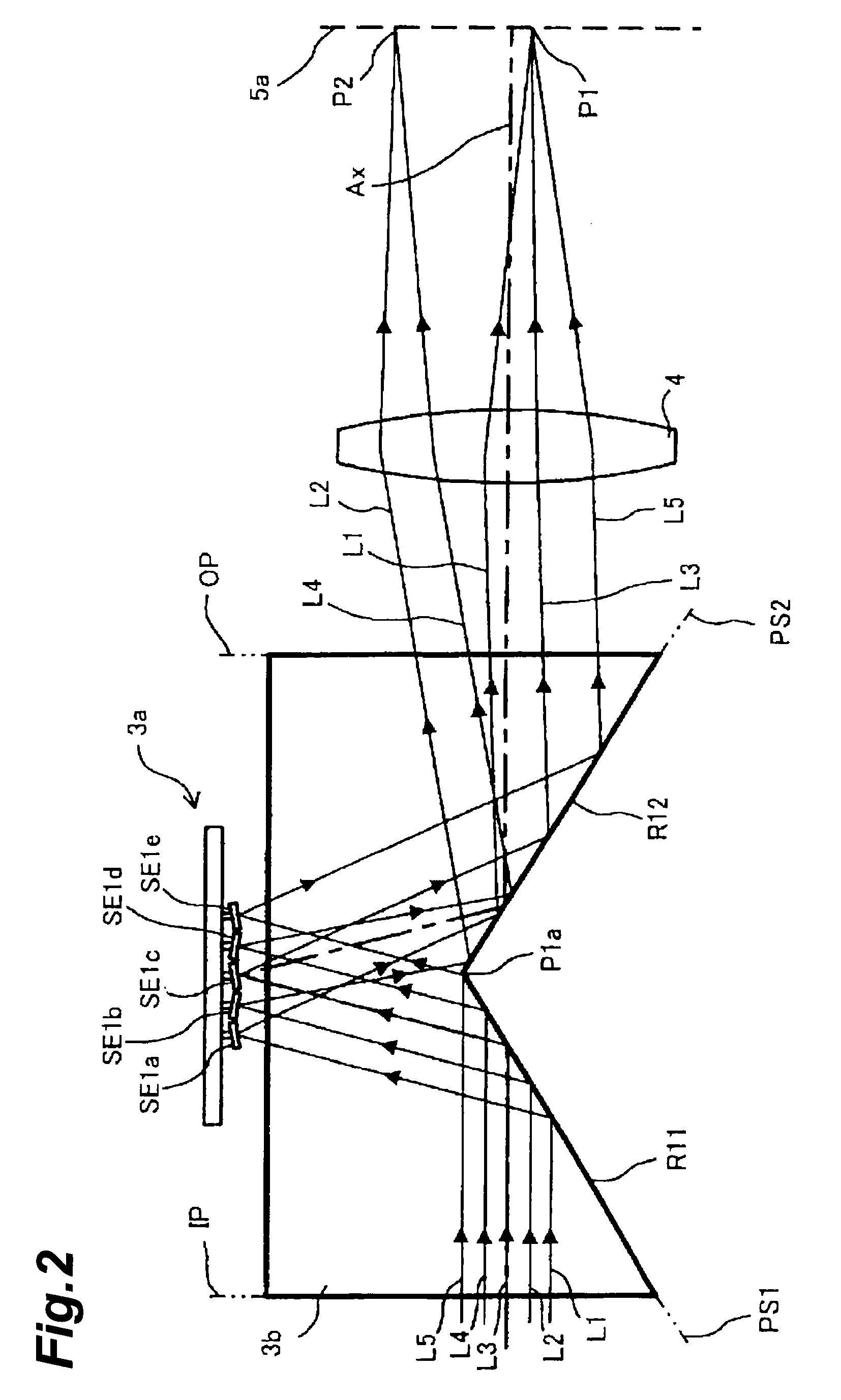
[0024]In the following, embodiments of the illumination apparatus, illumination method, exposure apparatus, and device manufacturing method according to the present invention will be described below in detail with reference to FIGS. 1 to 3, 3A to 3D, 4, 5A, 5B and 6 to 7. In the description of the drawings, the same portions and the same elements will be denoted by the same reference symbols, without redundant description.

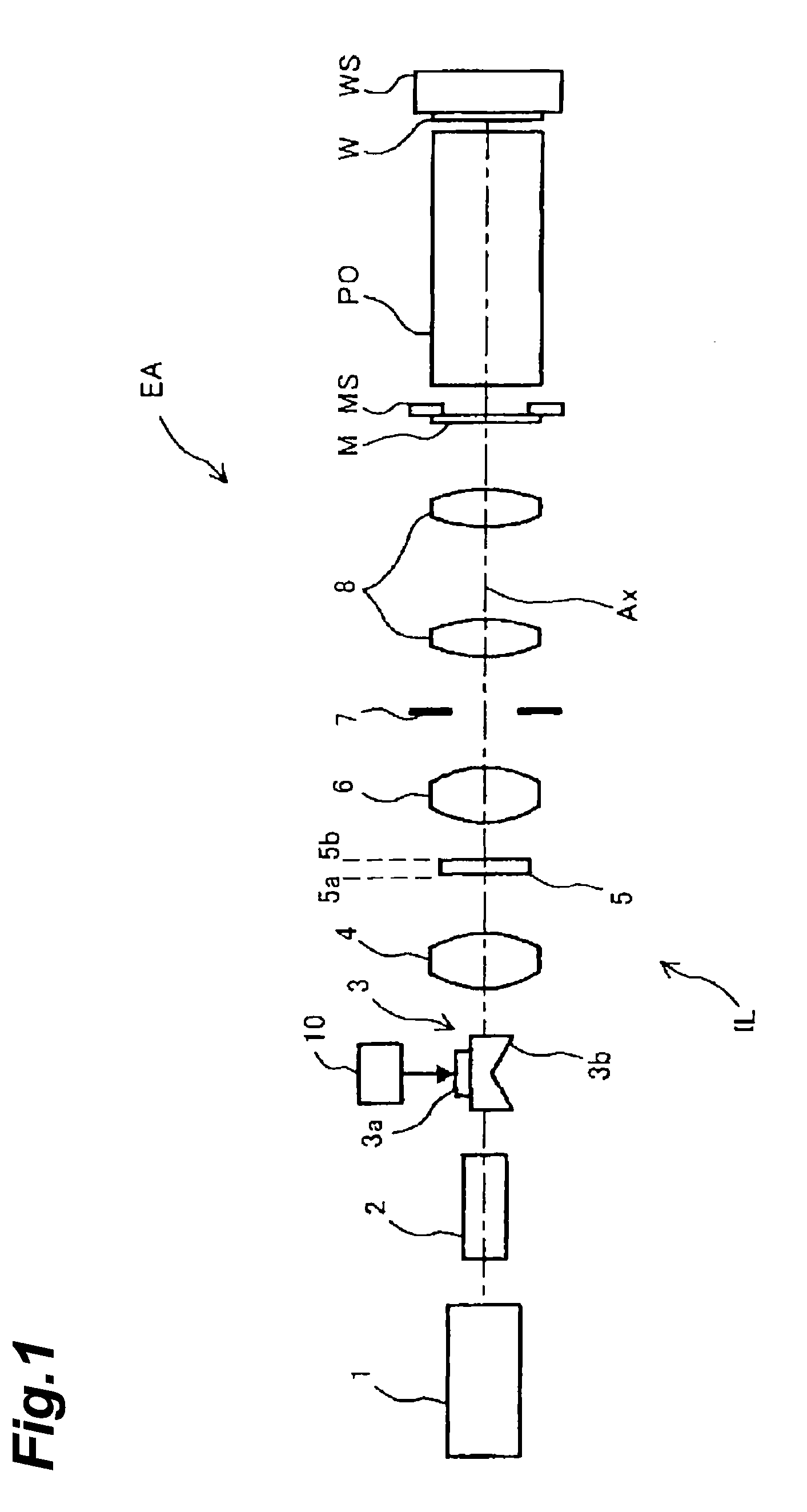
[0025]FIG. 1 is a drawing schematically showing a configuration of the exposure apparatus according to an embodiment of the present invention. In FIG. 1, the Z-axis is set along a direction of a normal to a wafer W being a photosensitive substrate, the Y-axis along a direction parallel to the plane of FIG. 1 in a plane of the wafer W, and the X-axis along a direction normal to the plane of FIG. 1 in the plane of the wafer W.

[0026]Referring to FIG. 1, the exposure apparatus EA has an illumination apparatus IL, a mask stage MS supporting a mask M, a projection optica...


PUM


Abstract

To optionally forming a multilevel light intensity distribution on an illumination pupil plane, the illumination apparatus implements Köhler illumination on an illumination target surface, using as a light source the light intensity distribution formed on the illumination pupil plane on the basis of light from a light source. The illumination apparatus has a spatial light modulator, a condensing optical system, and a control unit. The spatial light modulator has a plurality of reflecting surfaces which are two-dimensionally arranged and postures of which can be controlled independently of each other. The condensing optical system condenses light from the reflecting surfaces to form a predetermined light intensity distribution on the illumination pupil plane. The control unit controls the number of reflecting surfaces contributing to arriving light, for each of points on the illumination pupil plane forming the light intensity distribution, according to a light intensity distribution to be formed on the illumination pupil plane.

Description

CROSS-REFERENCE TO RELATED APPLICATION[0001]This application is based upon and claims the benefit of priority (priorities) from Provisional Application No. 60 / 996,295 filed on Nov. 9, 2007, the entire contents of which are incorporated herein by reference.BACKGROUND OF THE INVENTION[0002]1. Field of the Invention[0003]An embodiment of the present invention relates to an illumination apparatus incorporating a spatial modulation unit for generating a predetermined light intensity distribution (pupil luminance distribution) on an illumination pupil plane on the basis of light from a light source, an illumination method using the spatial modulation unit, an exposure apparatus incorporating the illumination apparatus, and a device manufacturing method using the exposure apparatus.[0004]2. Related Background Art[0005]A reflection-type spatial light modulator is hitherto known as a spatial modulator to form a pupil luminance distribution for modified illumination (e.g., a dipolar, quadrupo...

Claims


Application Information

Patent Timeline
Patent Type & Authority Applications(United States)
IPC IPC(8): G02B26/02
CPCG02B26/0833G02B27/0905G03F7/70116G03F7/70108G03F7/70075G02B26/02G03F7/70058
Inventor TANITSU, OSAMU
Owner NIKON CORP
Why Eureka
Try Eureka