Machine tool

a technology of machine tools and chucks, which is applied in the direction of chucks, turning machine accessories, work transfer apparatus, etc., can solve the problems of large devices, increased apparatus costs, and difficulty in precise machining of workpiece inclined faces, so as to shorten the time required for a series of operations and achieve powerful and accurate operation of chucking units.

Active Publication Date: 2009-05-07
STAR MICRONICS
View PDF4 Cites 25 Cited by
  • Summary
  • Abstract
  • Description
  • Claims
  • Application Information

AI Technical Summary

Benefits of technology

[0017]With this arrangement, a front-machining operation is performed on the workpiece chucked by the main spindle by using the first tool attached to the tool spindle. The workpiece, one of whose ends (front-end) has been machined, is carried by the chucking unit attached to the tool spindle to a position where the second tool of the tool post is possibly applied, then a back-machining operation is performed on the other end of the workpiece. As described above, according to the present invention, without providing the conventional backworking attachment, front and back-machining operations can be performed on the workpiece. Accordingly, the entire apparatus can be downsized and the apparatus cost can be reduced. Since the tool spindle is pivotable, a precise machining on an inclined face is easily available in both front and back-machining operations.
[0021]With this arrangement, the workpiece is delivered to a neighborhood of the tool spindle by the workpiece carrier and the workpiece is picked up by the tool spindle from the workpiece carrier (pallet) and delivered to the main spindle. The finished workpiece can be returned to the workpiece carrier (pallet) by the tool spindle. Therefore, time required for a series of operations can be shortened including the delivery of the pre-machined workpiece to the main spindle and the return of the finished workpiece to the pallet.
[0022]As another embodiment of the present invention, the tool spindle supplies pressurized coolant to the chucking unit through a supply passage formed in the tool spindle and the chucking unit is opened and closed according to the supply of the coolant. High-pressure coolant is much stronger than compressed air in pressure applied to the chucking unit. Therefore, powerful and accurate operation of the chucking unit is available.

Problems solved by technology

Therefore, the device is very large.
Therefore, the apparatus cost is raised.
Since movement of the main spindle is limited as described above, it is difficult to operate precise machining on an inclined face of the workpiece.
Therefore, a machining ability is not sufficient.
Accordingly, the apparatus cost is raised.
Therefore, the apparatus becomes large in its configuration and further the cost is raised.

Method used


Image

  • Machine tool
  • Machine tool
  • Machine tool

Examples


Embodiment Construction

[0037]Referring to the drawings, embodiments of the present invention will be explained.

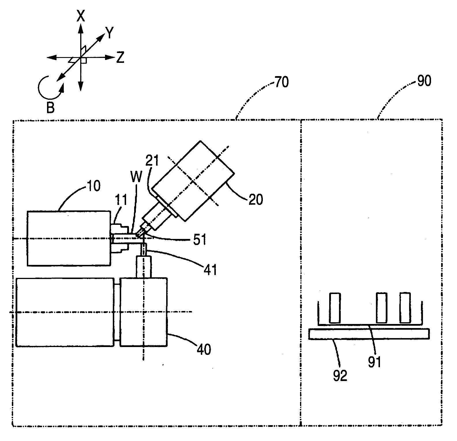
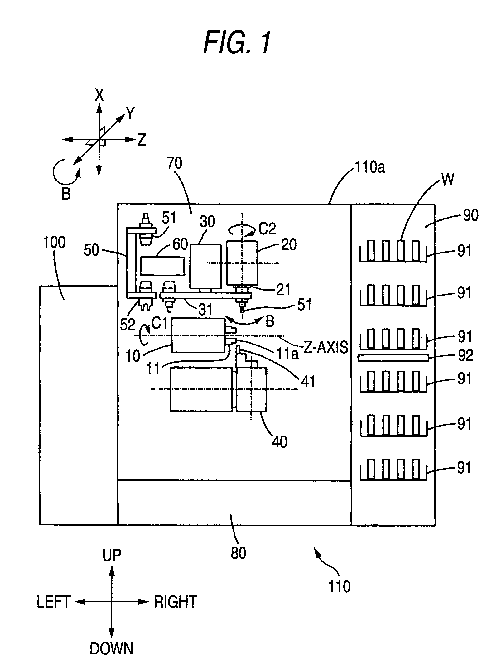
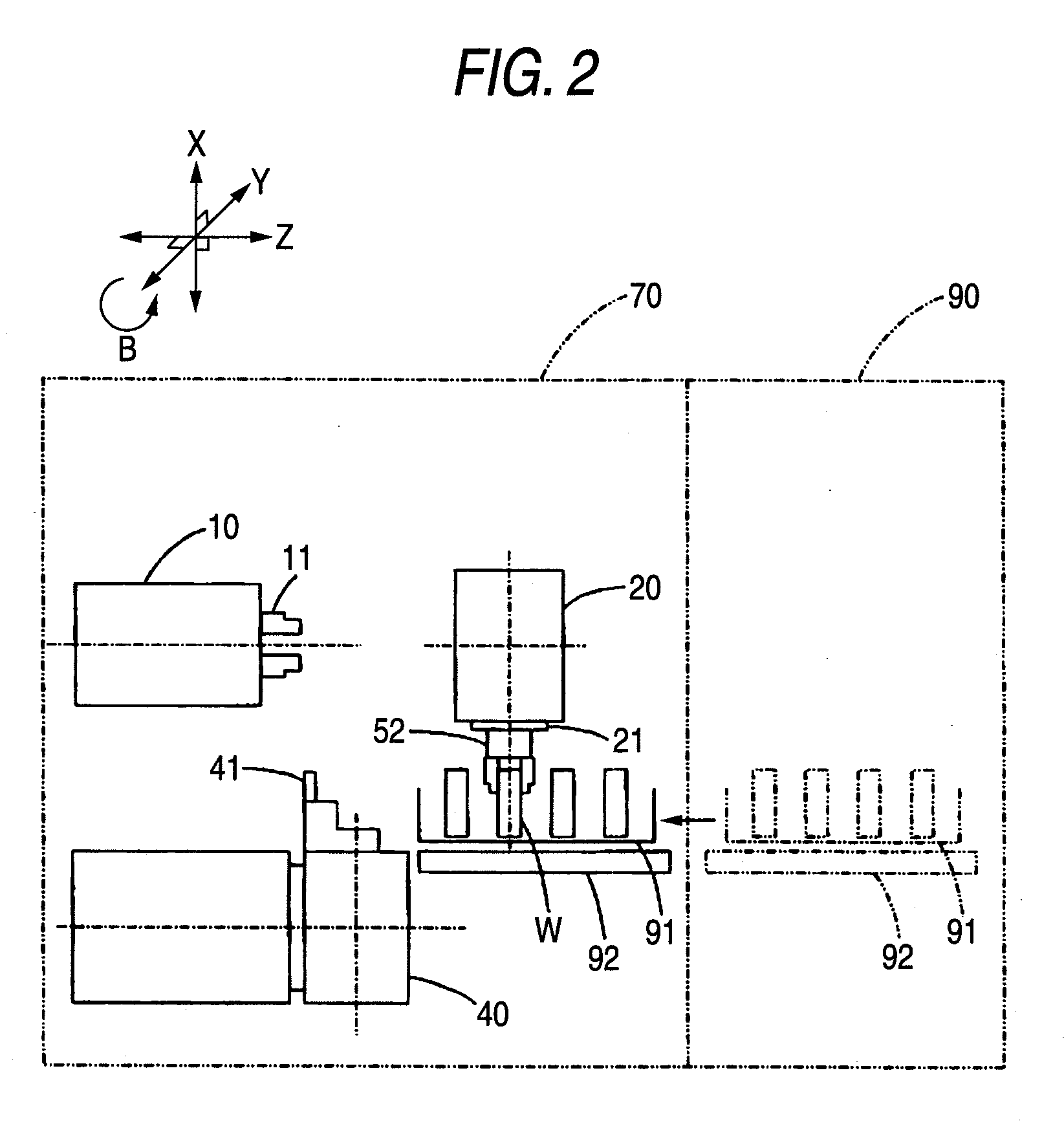
[0038]FIG. 1 is a schematic illustration showing a configuration of an NC lathe 110 of the present embodiment, wherein the configuration is exemplarily showing from one side. The NC lathe 110 is one type of machine tools. A machining chamber 70, a coolant tank 80, and a pallet station 90 are provided in a housing 110a of the NC lathe 110. A headstock 10, a tool spindle stock 20, an ATC (Automatic Tool Changer) 30, a tool post 40, a tool magazine 50 and an intermediate station 60 are respectively arranged at predetermined positions in the machining chamber 70.

[0039]In an example shown in FIG. 1, the coolant tank 80 is provided in a lower part of the machining chamber 70 and stores coolant inside. The pallet station 90 is provided being adjacent to the machining chamber 70 to accommodate a plurality of pallets 91. The pallet 91 is configured to carry a workpiece W inside and outside the machining c...


PUM

PropertyMeasurementUnit
pressureaaaaaaaaaa
sizeaaaaaaaaaa
lengthsaaaaaaaaaa

Abstract

A machine tool includes: a main spindle adapted to be rotatable with a workpiece chucked thereby; a tool spindle capable of moving in directions of three axes perpendicular to each other and capable of pivoting about one of the axes, the axis being perpendicular to the main spindle; an automatic tool changer adapted to detachably attach a first tool and a chucking unit to the tool spindle, the first tool being used for machining the workpiece chucked by the main spindle, the chucking unit being used for chucking the workpiece; and a tool post having a second tool mounted thereon, the second tool being used for machining the workpiece chucked by the chucking unit attached to the tool spindle.

Description

BACKGROUND[0001]1. Field of the Invention[0002]The present invention relates to a machine tool.[0003]2. Description of the Related Art[0004]A machine tool such as a numerical control lathe (NC lathe) is conventionally used to manufacture desired precision parts by performing front-machining and back-machining operations on a workpiece.[0005]FIG. 12 is a schematic illustration showing a conventional NC lathe 1. The NC lathe 1 includes: a headstock 3 having a main spindle 2 chucking a workpiece W for a front-machining operation; and a backworking attachment 4 opposed to the headstock 3 in a direction of the main spindle 2 (in a direction of Z-axis). The backworking attachment 4 includes a sub spindle 5 for chucking the workpiece W for a back-machining operation. The NC lathe 1 includes a tool spindle stock 7 having a tool spindle 6. The main spindle 2 and the sub spindle 5 is under rotation control about Z-axis (C1-axis control) by a computer (not shown) according to a predetermined p...

Claims


Application Information

Patent Timeline
Patent Type & Authority Applications(United States)
IPC IPC(8): B23B51/00
CPCB23B3/065Y10T483/17B23B31/16254B23Q7/045B23Q7/047B23Q39/026B23Q2230/006Y10T483/171Y10T29/5109Y10T483/1705Y10T82/2506Y10T82/2524Y10T483/16Y10T82/2514B23B3/30B23B25/04B23Q3/155B23Q3/16B23Q16/00
Inventor KAWASUMI, MASAHIROOZAWA, SATORU
Owner STAR MICRONICS
Why Eureka
Try Eureka