

End-Tidal Gas Estimation System and Method
- Summary
- Abstract
- Description
- Claims
- Application Information
AI Technical Summary
Benefits of technology
Problems solved by technology
Method used
Image

Examples
Embodiment Construction
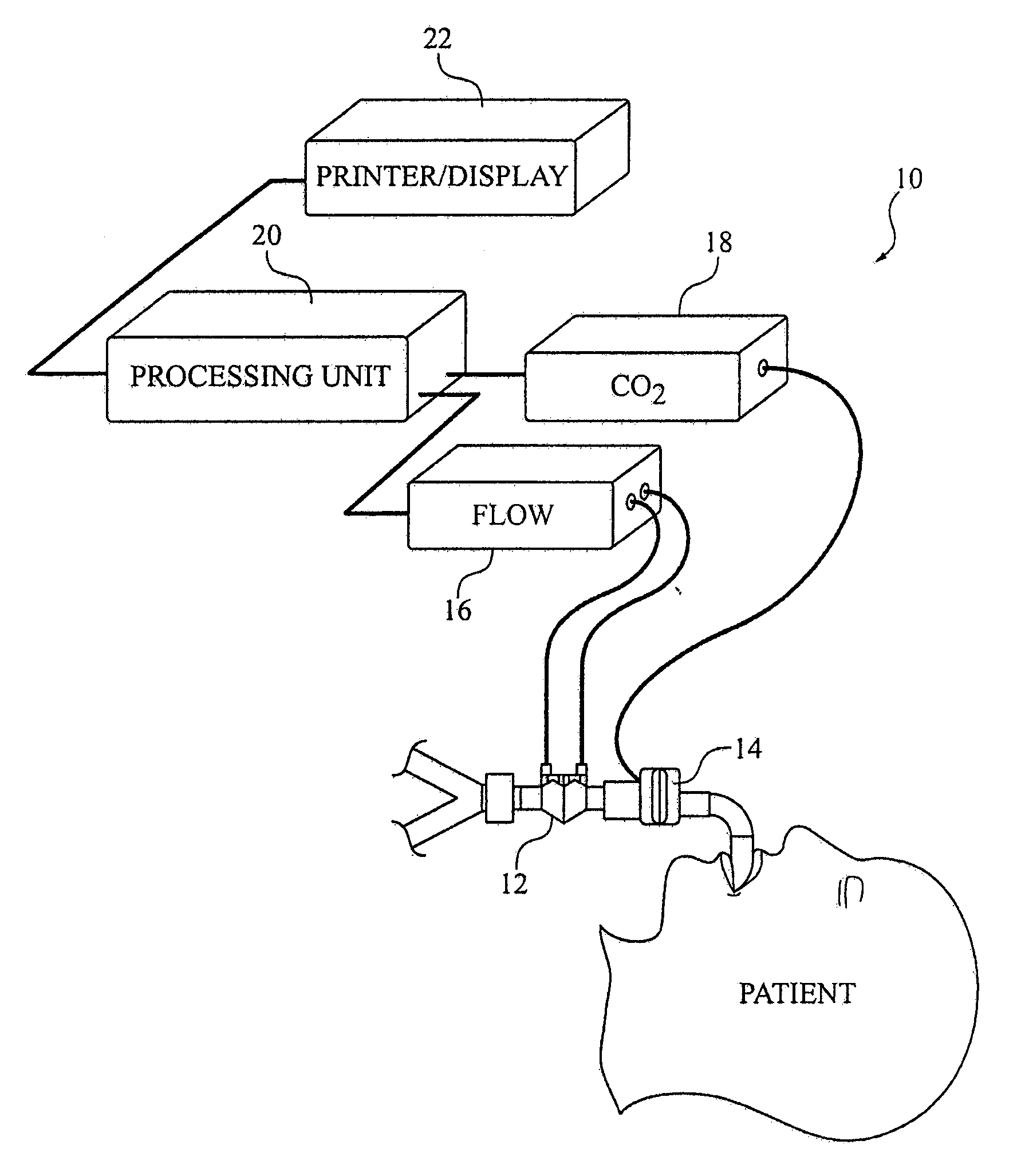
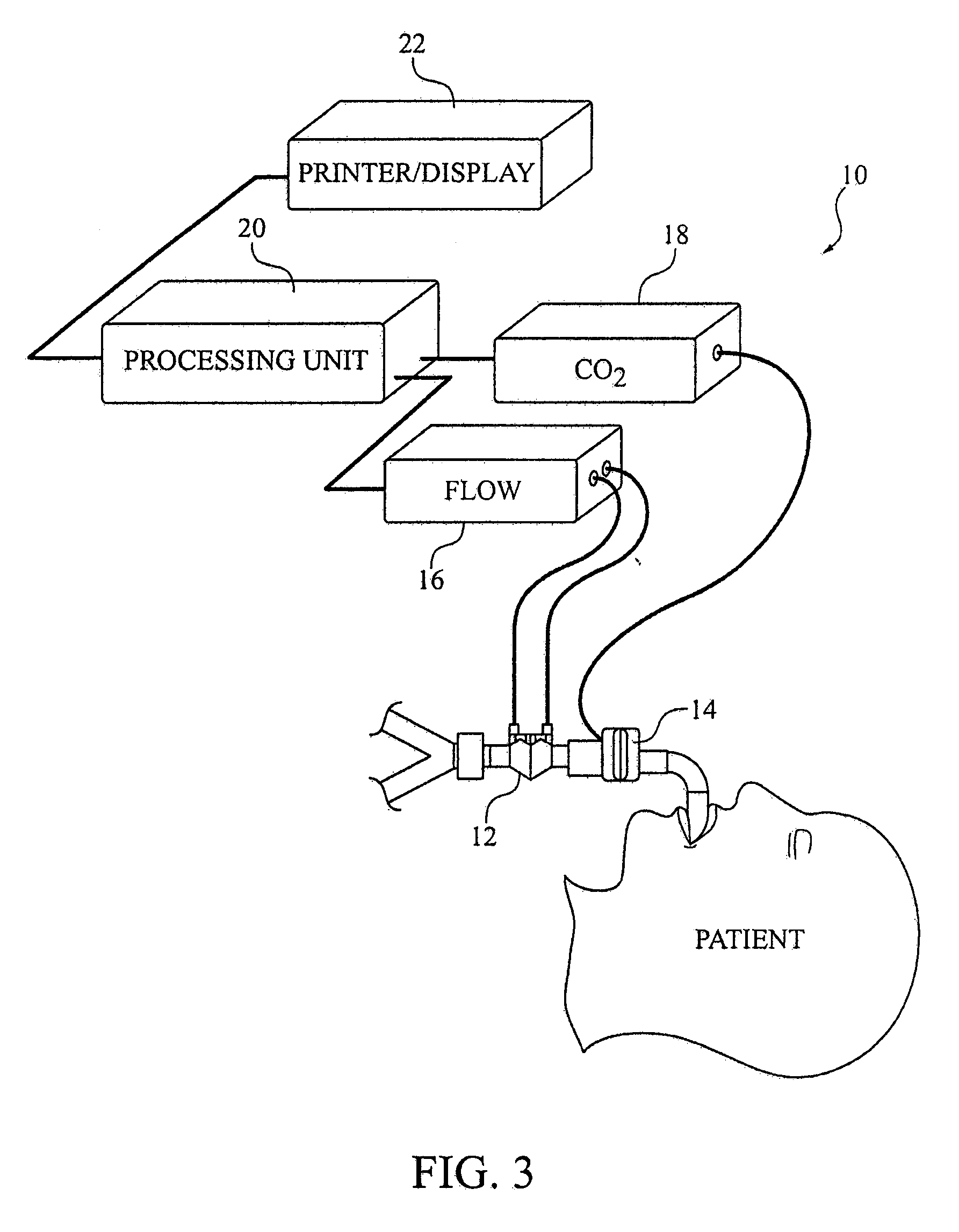
[0032]The present invention addresses the known problems with the studies to date including (a) the lack of a clear definition of end-tidal gas value, (b) how end-tidal gas values relate to arterial gas values in both ‘stable’ and ‘unstable’ ventilatory patterns, and, (c) an understanding of when end-tidal gas values will and won't be a reliable correlate of arterial and or alveolar gas values. The present invention addresses the need to provide more reliable end-tidal gas values. It should be noted that the while most of the present discussion takes place with reference to carbon dioxide (CO2), the methods described herein apply to other gases as well, including but not limited to respiratory gases, such as oxygen, nitrous oxide, nitric oxide, and other gases, such as anesthetic agents. To determine a more reliable end-tidal gas value, it is important to delineate properly the end-tidal gas value and to determine the reliability of that estimate.
[0033]An exemplary embodiment of a g...
PUM
 Abstract
Description
Claims
Application Information