Configuration optimization method for a storage system

a storage system and optimization method technology, applied in the direction of memory address/allocation/relocation, sustainable buildings, instruments, etc., can solve the problems of difficult to set the registered pool volume to the sleep state, inability to achieve the power saving effect, so as to reduce the power saving effect and high incidence of spinups

Active Publication Date: 2009-05-07
HITACHI LTD
View PDF7 Cites 39 Cited by
  • Summary
  • Abstract
  • Description
  • Claims
  • Application Information

AI Technical Summary

Benefits of technology

[0010]According to the above-mentioned conventional examples, an I / O from the host computer to a virtual volume is balanced among pool volumes of a pool associated with the virtual volume. Accordingly, once a pool volume is registered for a pool, the pool volume is frequently accessed, which leads to a problem that a power saving effect cannot be attained even when the method according to JP 2005-157710 A is adopted in the case of using the technology according to JP 2003-15915 A. In other words, parallel access is made to the pool volume registered for the pool, which leads to a problem that it is difficult to set the registered pool volume to the sleep state. Further, even when the technology according to JP 2005-157710 A is applied to the pool volume, the sleep state can be set for a short period, leading to a high incidence of spinups in the pool volume, and there occurs a problem, due to the high incidence of spinups, that the power saving effect is reduced and the high incidence of spinups further causes a deterioration in the responsivity of the pool.

Problems solved by technology

Accordingly, once a pool volume is registered for a pool, the pool volume is frequently accessed, which leads to a problem that a power saving effect cannot be attained even when the method according to JP 2005-157710 A is adopted in the case of using the technology according to JP 2003-15915 A. In other words, parallel access is made to the pool volume registered for the pool, which leads to a problem that it is difficult to set the registered pool volume to the sleep state.
Further, even when the technology according to JP 2005-157710 A is applied to the pool volume, the sleep state can be set for a short period, leading to a high incidence of spinups in the pool volume, and there occurs a problem, due to the high incidence of spinups, that the power saving effect is reduced and the high incidence of spinups further causes a deterioration in the responsivity of the pool.
The above-mentioned problems always occur, not only in the case of using the technology according to JP 2003-15915 A, but also in a case of using any technology in which storage regions are formed in a group and parallel access is made thereto.
Further, the above-mentioned problems similarly occur in a case of grouping storage regions based on any other criterion than the criterion on power saving, such as a criterion on response performance of the storage region, a criterion on costs, and a criterion on access parallelism.

Method used


Image

  • Configuration optimization method for a storage system
  • Configuration optimization method for a storage system
  • Configuration optimization method for a storage system

Examples


first embodiment

A. First Embodiment

[0041]A1. System Configuration

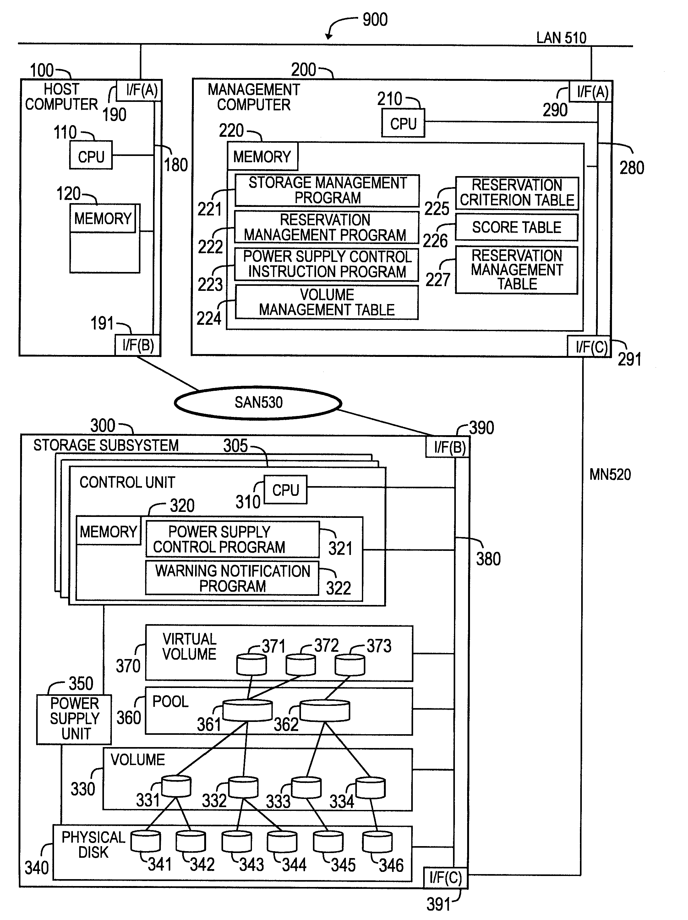
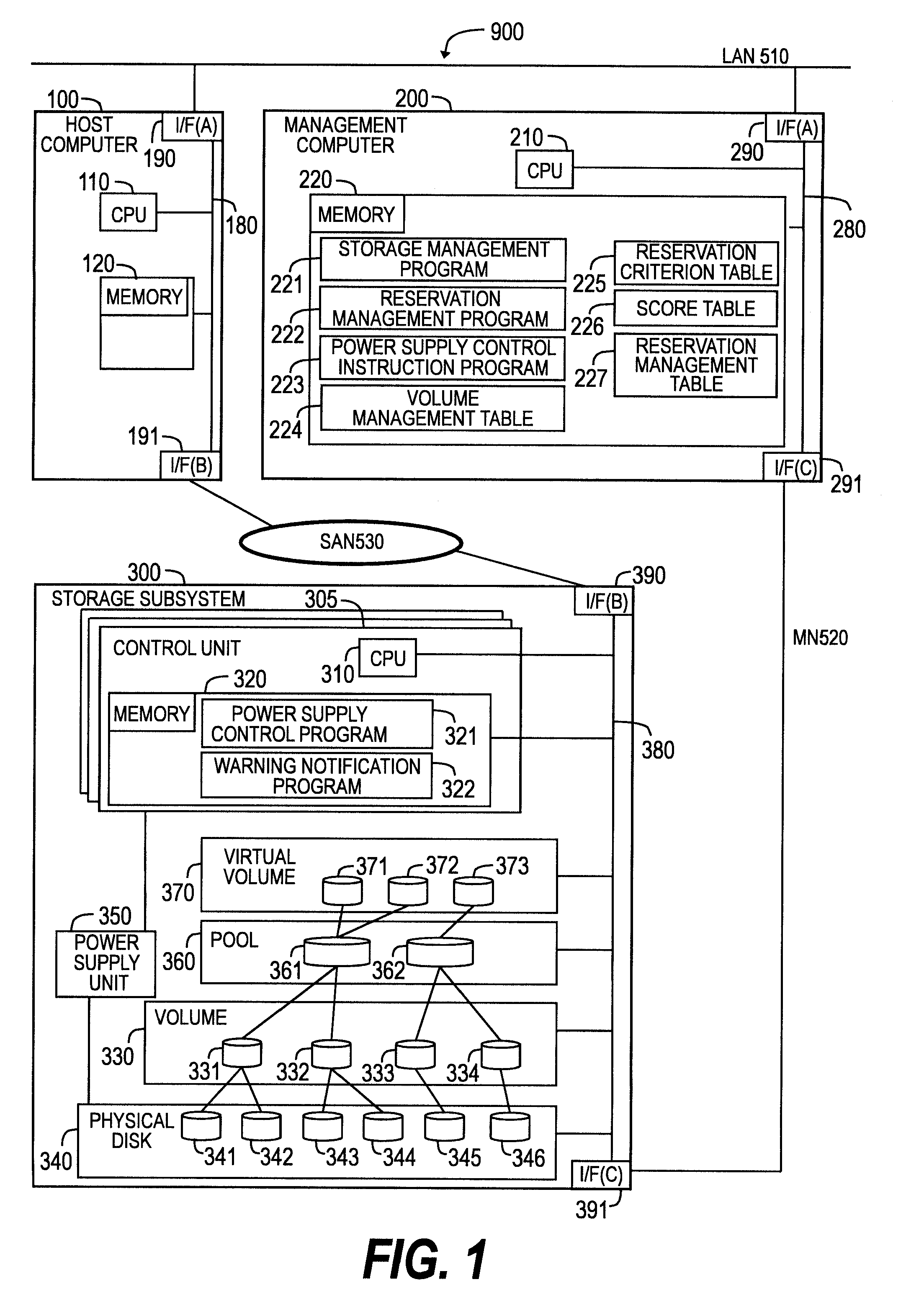
[0042]FIG. 1 is a block diagram illustrating a configuration of a data processing system according to a first embodiment of this invention. The data processing system 900 includes at least each one of a host computer 100, a management computer 200, and a storage subsystem 300.

[0043]The host computer 100 and the management computer 200 are coupled to each other via a local area network (LAN) 510. The host computer 100 and the storage subsystem 300 are coupled to each other via a storage area network (SAN) 530. The management computer 200 and the storage subsystem 300 are coupled to each other via a management network (MN) 520.

[0044]The host computer 100 includes a central processing unit (CPU) (also referred to as processor) 110, a memory 120, a network interface I / F (A) 190 for coupling to the LAN 510, and a network interface I / F (B) 191 for coupling to the SAN 530. Those constituent elements are coupled to one another via a bus 180.

[...

second embodiment

B. Second Embodiment

[0134]B1. System Configuration

[0135]FIG. 12 is an explanatory diagram illustrating a configuration of a data processing system 900b according to a second embodiment of this invention. The data processing system 900b includes at least each one of the host computer 100, a management computer 200b, a storage subsystem 300b, and a storage subsystem 400. The configuration of the second embodiment is similar in most part to the configuration of the first embodiment, and therefore only the difference in configuration will be described hereinafter.

[0136]The differences between the data processing system 900 of the first embodiment shown in FIG. 1 and the data processing system 900b of the second embodiment reside in that the storage subsystem 300b includes an external connection program 323 on the memory 320, in that the data processing system 900b includes the storage subsystem 400, and in that the management computer 200b includes a volume management table having exter...

third embodiment

C. Third Embodiment

[0150]C1. System Configuration

[0151]FIG. 16 is an explanatory diagram illustrating a configuration of a data processing system 900c according to a third embodiment of this invention. The data processing system 900c includes at least each one of the host computer 100, a management computer 200c, and the storage subsystem 300. The configuration of the third embodiment is similar in most part to the configuration of the first embodiment, and therefore merely the difference will be described hereinafter.

[0152]The difference between the data processing system 900 shown in FIG. 1 and the data processing system 900c of the third embodiment of this invention resides in that the management computer 200c includes a volume status table 228 and a volume replacing program 229 on the memory 220.

[0153]The volume status table 228 includes, as shown in FIG. 17, a device ID 2280 for identifying a storage subsystem 300, a logical unit number (LUN) 2281 which is an identification num...


PUM


Abstract

This invention provides, when optimizing a configuration of a storage system using a pool, an optimal configuration while ensuring a policy set by an administrator, the policy concerning a power saving performance, a response performance, or the like. The management computer sets, according to the set policy, priorities to volumes held by a storage subsystem, and reserves volumes satisfying the capacity of the pool, in descending order of the priority. Only some of the reserved volumes are registered for the pool in descending order of the priority. At this time, it can be guaranteed that a host computer makes no access to the volumes which have not been registered for the pool, and therefore the sleep state is set to physical drives forming the volumes or to a controller controlling the physical drives.

Description

CLAIM OF PRIORITY[0001]The present application claims priority from Japanese application P2007-285932 filed on Nov. 2, 2007, the content of which is hereby incorporated by reference into this application.BACKGROUND OF THE INVENTION[0002]This invention relates to configuration management for a storage system, and more particularly to a configuration optimization method for a storage system.[0003]In recent years, there is a rapid increase in data amount to be handled by a company or an individual. Along with this, a storage system using a technology such as a storage area network (SAN) or a network attached storage (NAS) is widely used. According to the technology, a storage subsystem or a host computer is coupled via a switch or a hub, to thereby manage data with flexibility.[0004]Further, in these days, along with the increase in size and the enhancement in performance of a storage system (hereinafter, also referred to as storage subsystem), power consumption in the storage subsyste...

Claims


Application Information

Patent Timeline
Patent Type & Authority Applications(United States)
IPC IPC(8): G06F12/02G06F1/32
CPCY02B60/1246G06F1/3221Y02D10/00
Inventor KONO, YASUTAKASHINOHARA, DAISUKEMAKI, NOBUHIROSAKASHITA, YUKINORI
Owner HITACHI LTD
Why Eureka
Try Eureka