
Modular transportable life support device

a life support device and transportable technology, applied in the field of portable medical treatment systems, can solve the problems of insufficient traditional response, difficult to reach locations, difficult to implement simultaneous control of multiple functions, etc., and achieve the effect of high flexibility and adaptability

Inactive Publication Date: 2009-05-14
MEDFLEX
View PDF99 Cites 15 Cited by
  • Summary
  • Abstract
  • Description
  • Claims
  • Application Information

AI Technical Summary

Benefits of technology

[0013]The present invention provides a portable suite of medical functionality for emergency response situations integrated into a single platform capable of enabling centralized operation and control over the integrated units. The central power, data, and / or pneumatic capabilities of the control spine provide power, data and pneumatic transfer as required by the modules. The modular architecture enables high flexibility and adaptability with regard to the medical functionality provided by the present invention.

Problems solved by technology

Although such a medical response is sufficient in most civilian applications, there may be extreme situations in which a traditional response is insufficient.
In the case of natural disasters and battlefield environments, patients may be located in remote, hard to reach locations.
However, while such contemporary systems offer certain economic advantages in reduced development costs, the resulting systems would likely suffer from many short-comings, such as wiring demands, difficulty in implementing simultaneous control over multiple functions, difficulties in supporting updates in various monitoring / treatment devices without modifying central processing and power distribution functions, and other factors affecting the simplicity, reliability and stability of the overall platform.

Method used


Image

  • Modular transportable life support device
  • Modular transportable life support device
  • Modular transportable life support device

Examples


Embodiment Construction

[0030]Set forth below is intended as a description of the presently preferred embodiment of the invention, and is not intended to represent the only form in which the present invention may be constructed or utilized. The description sets forth the functions and sequences of steps for constructing and operating the invention. It is to be understood, however, that the same or equivalent functions and sequences may be accomplished by different embodiments and that they are also intended to be encompassed within the scope of the invention.

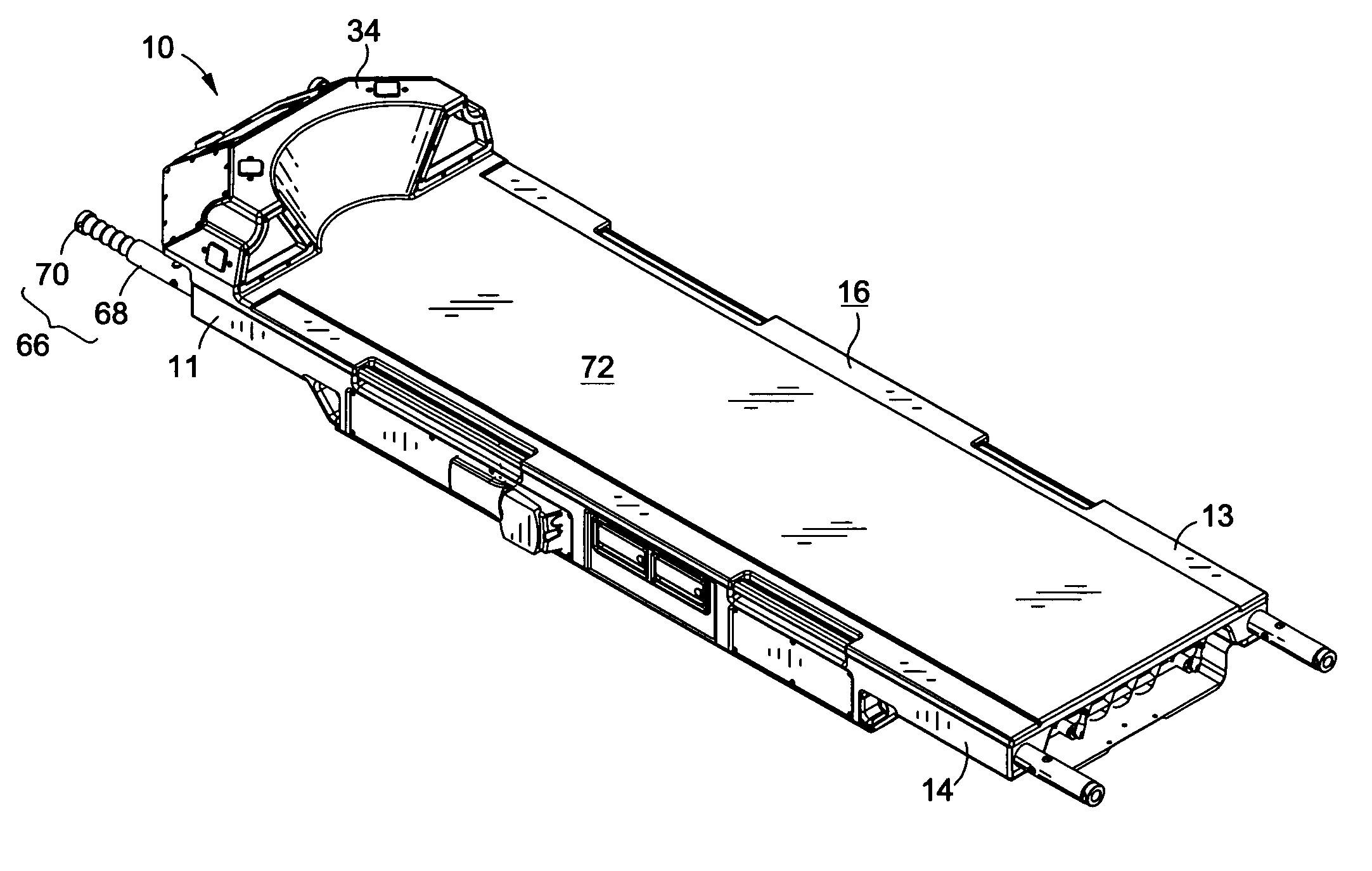
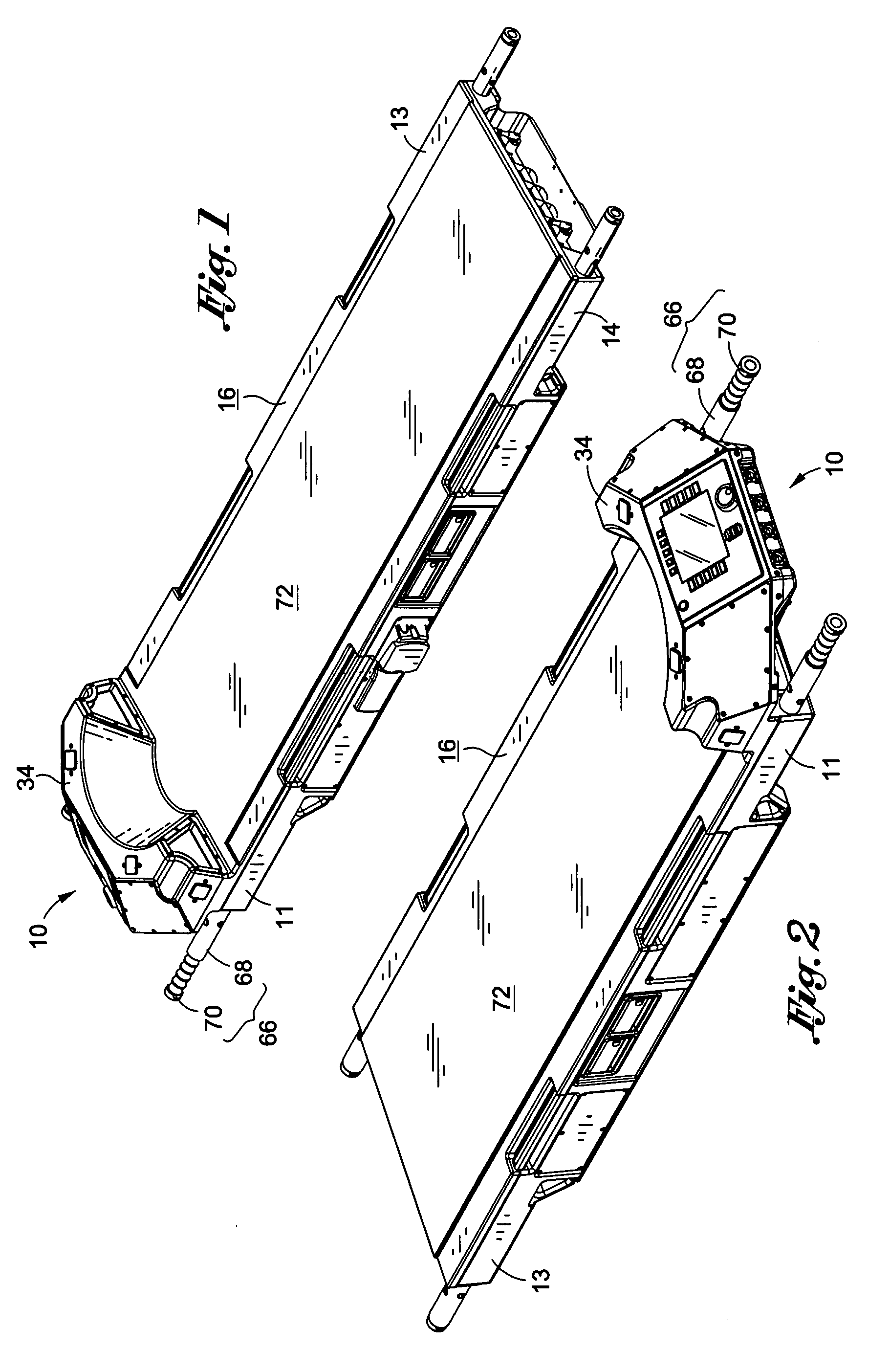
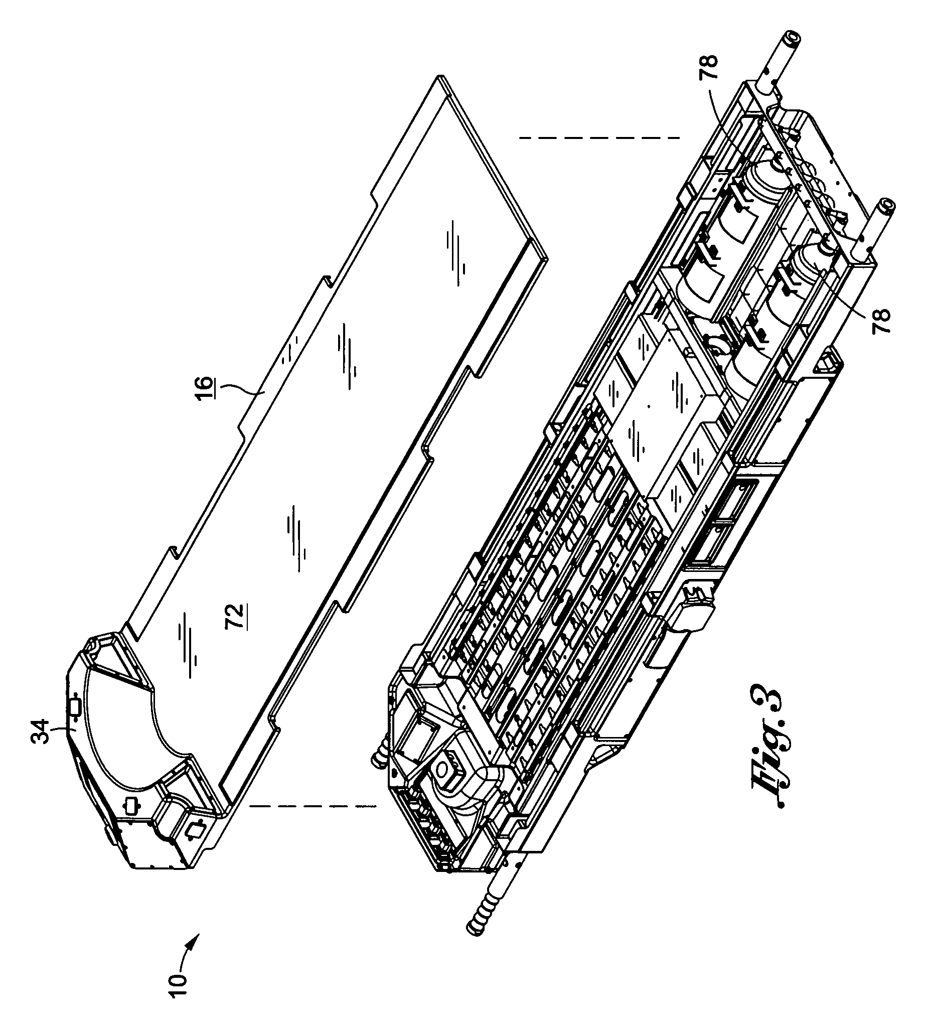
[0031]Referring now to FIGS. 1-12 and according to an embodiment of the present invention, there is provided a patient care and treatment platform 10 configured to provide centralized operation and control capabilities for a plurality of modular medical units. The platform 10 includes a housing 14 and a patient support surface 16 disposed thereon. The platform housing 14 may include a head portion 11 and a foot portion 13. The patient support surface 1...


PUM


Abstract

There is provided a patient care and treatment platform that is connectable to a plurality of modules capable of providing medical functionality. The platform includes a housing and a patient support surface. The platform also includes a power receiver for receiving power. The platform further includes a module interface including power, data, and pneumatic spines having power data and pneumatic ports, respectively. The spines are operative to transfer data, power, and fluid within the platform. The ports are connectable to the modules to integrate the modules into the platform. The platform also includes a head fairing having a patient interface panel. The head fairing includes an inner surface that is substantially concave in shape and slopes away from the patient support surface to allow access to the head of a patient. The patient interface panel includes a plurality of ports connectable to electrical and pneumatic apparatus.

Description

CROSS-REFERENCE TO RELATED APPLICATIONS[0001]Not ApplicableSTATEMENT RE: FEDERALLY SPONSORED RESEARCH / DEVELOPMENT[0002]Not ApplicableBACKGROUND[0003]The present invention relates to portable medical treatment systems, including a plurality of patient monitoring / treatment devices. More particularly, the invention relates to a patient care and treatment device capable of hosting a suite of medical monitoring / treatment modules useful to treat a patient and adaptable to function in various environments, including full service hospitals, field stations or in medical transport.[0004]Many people suffer from injury and disease and require immediate medical attention. In many cases, an emergency response team is called to the patient's location for transport to a medical facility. The emergency response team may begin diagnosing and treating the patient for his injury or disease while en route. Although such a medical response is sufficient in most civilian applications, there may be extreme...

Claims


Application Information

Patent Timeline
Patent Type & Authority Applications(United States)
IPC IPC(8): A61G7/00
CPCA61B19/0248A61G2203/46A61G1/06A61G1/04A61B50/10
Inventor KNEALE, TODD DOUGLASALEXANDER, STEVEN BRUCEDOMAE, TERRANCE PAULQUILLEN, JOHN WILLIAMBONGIOVANNI, RICHARD ANTHONYBARNETT, PETER ANDREW
Owner MEDFLEX
Learn More