Electric cleaner

a vacuum cleaner and electric technology, applied in vacuum cleaners, vacuum cleaners, climate sustainability, etc., can solve the problems of limited size of detectable dust, difficult to determine the width of pulses with respect to large dust, and limited number of pulses of signal detection. achieve the effect of high accuracy

Inactive Publication Date: 2009-05-14
PANASONIC CORP
View PDF9 Cites 17 Cited by
  • Summary
  • Abstract
  • Description
  • Claims
  • Application Information

AI Technical Summary

Benefits of technology

[0006]In view of the above-described problems, the present invention has an object of providing an electric vacuum cleaner capable of controlling dusts of different sizes with high accuracy.

Problems solved by technology

However, the sizes of the detectable dusts are found to be limited by the circuit characteristics of the pulse converter which detects the size of the dust from the pulse width.
For one thing, house dusts which can be collected by a vacuum cleaner have a difference in area of several thousand times. Therefore, when the characteristics of the detection circuit (especially the amplification factor and frequency characteristics of the detection signal) are adjusted to small dusts, the number of pulses of the signal can be detected but the pulse width is difficult to determine with respect to large dusts.
In contrast, when the characteristics of the detection circuit are adjusted to large dusts, it is difficult to detect reaction with respect to small dusts.
In addition, the transit speed tends to be delayed with respect to the air intake speed.
This means that the conventional electric vacuum cleaners cannot efficiently control dusts of sizes other than the size to which the characteristics of the detection circuit have been adjusted.

Method used


Image

  • Electric cleaner
  • Electric cleaner
  • Electric cleaner

Examples


first embodiment

[0075]A first embodiment of the present invention is described as follows with reference to drawings.

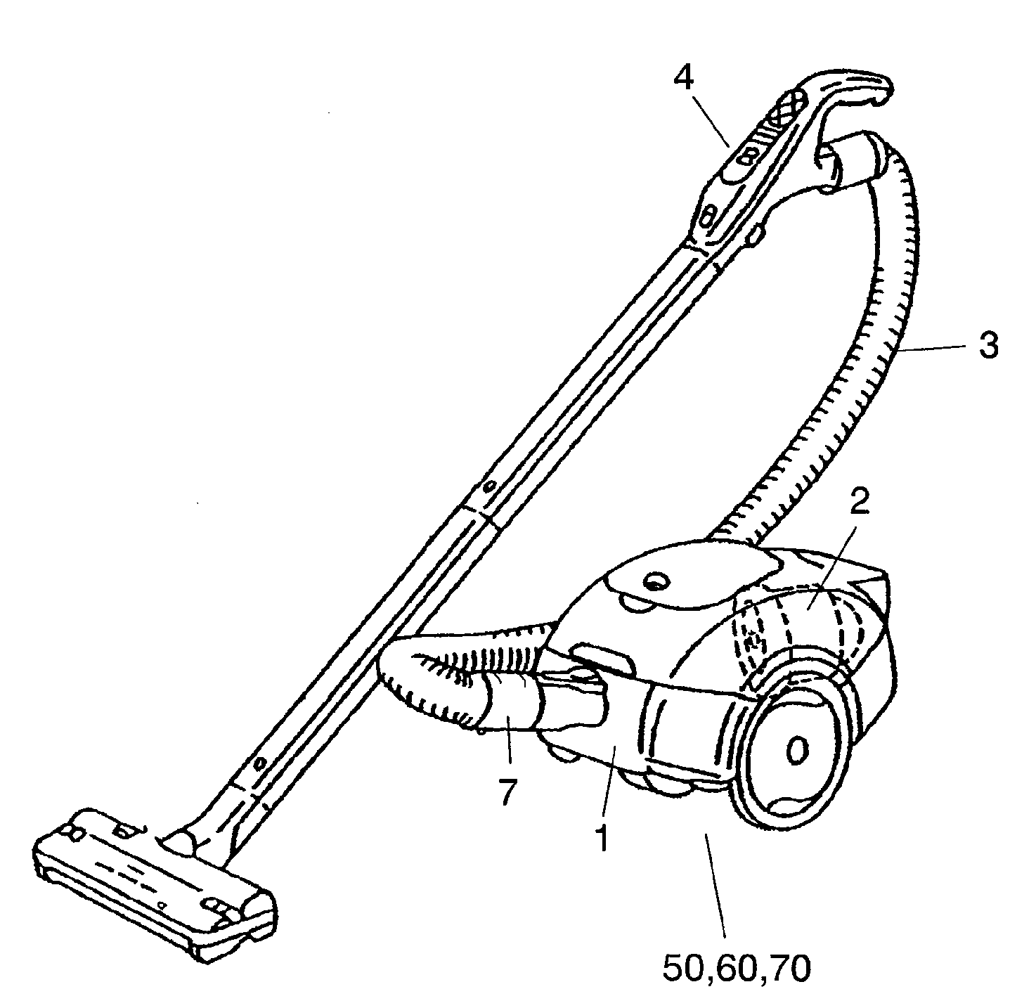
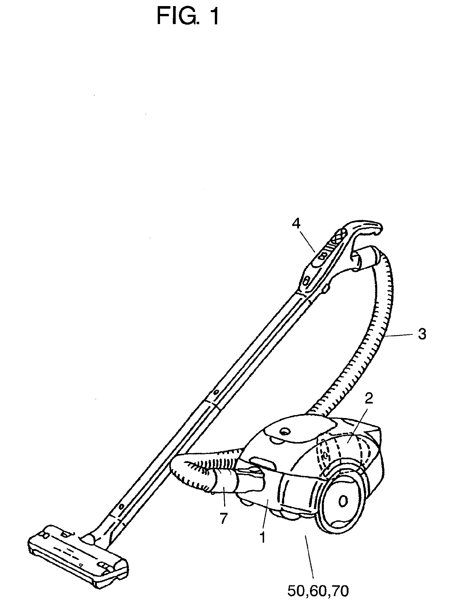
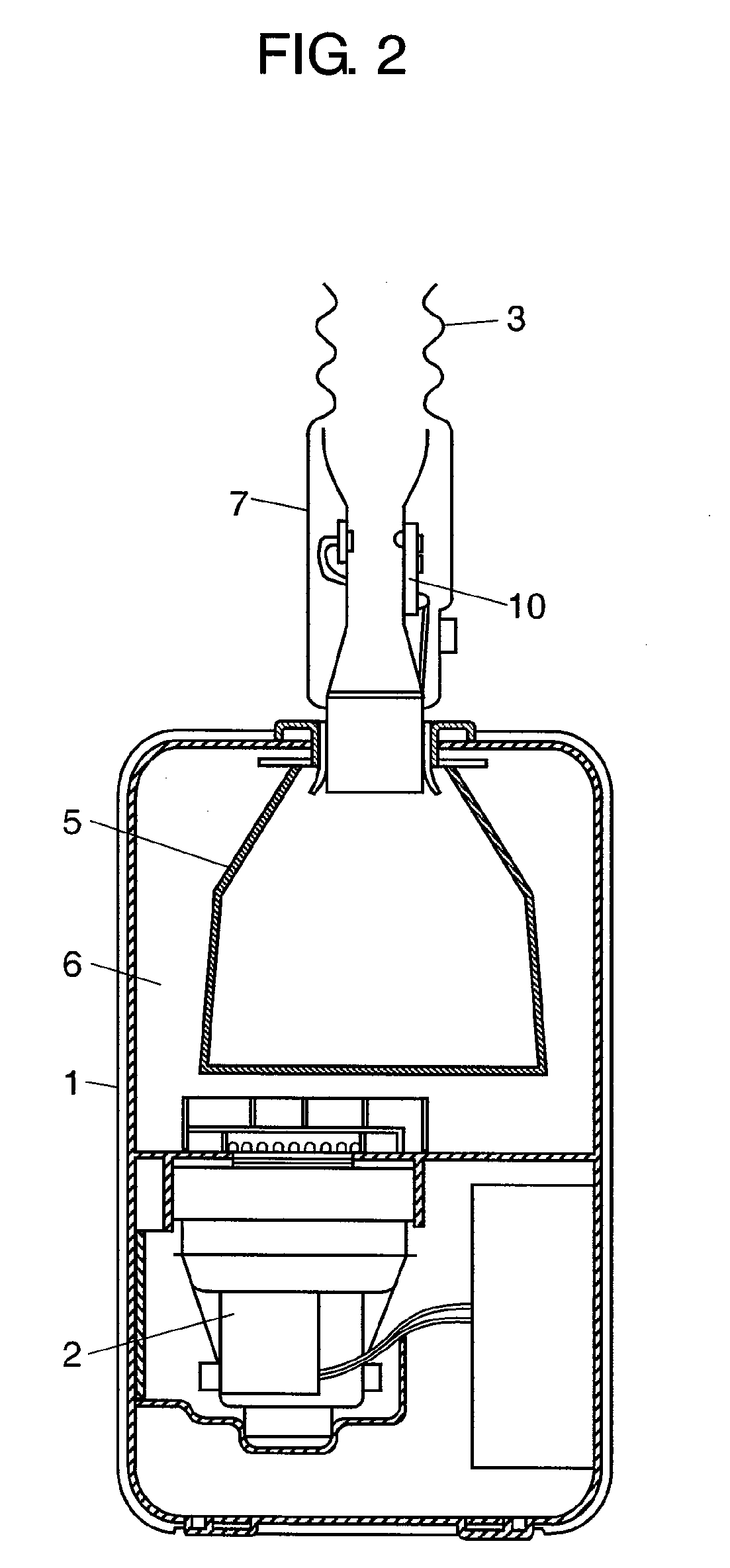
[0076]FIG. 1 is a perspective view of the appearance of electric vacuum cleaners 50, 60, and 70 according to the embodiments of the present invention. FIG. 2 is a schematic sectional view of electric vacuum cleaners 50, 60, and 70. Electric vacuum cleaner body 1 (hereinafter, body 1) houses electric blower 2 for generating suction power. Body 1 is connected to hose 3 having operating part 4 to be operated by the user. Body 1 further includes dust chamber 6 including dust bag 5.

[0077]Hose 3 includes dust detector 7 having first dust detector 10 and second dust detector 11 which will be described later. FIG. 3 is a schematic sectional view of dust detector 7 of the electric vacuum cleaners 50, 60, and 70.

[0078]FIG. 4 is a block diagram of the control system of electric vacuum cleaner 50 according to a first embodiment of the present invention. Body 1 includes driver 8 and determination...

second embodiment

[0115]A second embodiment of the present invention is described as follows with reference to drawings. FIG. 6 is a block diagram showing the control system of electric vacuum cleaner 60 according to the second embodiment. FIG. 7 is a flowchart showing an example of the dust detection signal processing of electric vacuum cleaner 60.

[0116]In the present embodiment, like components are labeled with like reference numerals with respect to the first embodiment, and the description of these components is not repeated.

[0117]Electric vacuum cleaner 60 includes first dust detector 40 having first amplifier-determiner 32 and second dust detector 41 having second amplifier-determiner 33. First dust detector 40 and second dust detector 41 are each composed of a transistor and one of a Zener diode and a resistor. First and second dust detectors 40 and 41 output signals whose voltages are changed to a plurality of voltage levels, thereby transmitting them as detection signals to dust amount senso...


PUM


Abstract

An electric vacuum cleaner includes an electric blower, a driver for driving the electric blower, a determination controller for controlling the electric power supply to the electric blower by transmitting a signal to the driver, and a dust amount sensor for sensing the amounts of dusts of different sizes. The determination controller controls the electric power supply to the electric blower based on the amounts of dusts of the different sizes sensed by the dust amount sensor.

Description

TECHNICAL FIELD[0001]The present invention relates to electric vacuum cleaners for household use.BACKGROUND ART[0002]In recent years, there have been proposed vacuum cleaners with various features. One such feature is to control the electric blower by detecting the amount of dust using a dust sensor disposed in an air passage through which dust is collected (see, for example, Examined Japanese Patent Publication No. H07-28847 and Japanese Patent No. 3006145).[0003]In the conventional electric vacuum cleaners, the number and the sizes of dusts are determined by the number of pulses and the pulse width, respectively, of a detection signal. However, the sizes of the detectable dusts are found to be limited by the circuit characteristics of the pulse converter which detects the size of the dust from the pulse width.[0004]The reasons of the limitation are as follows. For one thing, house dusts which can be collected by a vacuum cleaner have a difference in area of several thousand times....

Claims


Application Information

Patent Timeline
Patent Type & Authority Applications(United States)
IPC IPC(8): A47L5/00
CPCA47L9/2815A47L9/2842Y02B40/82A47L9/2894A47L9/2857Y02B40/00A47L9/28
Inventor SENOO, HIROYUKIISHIBASHI, TAKAFUMIOHSHIMA, YASUOUENO, SEIICHIITOH, AKIHITO
Owner PANASONIC CORP
Why Eureka
Try Eureka