
Stackable nursery trays for plants

a technology for plants and trays, applied in the field of trays for plants, can solve the problems of limited space where the trays are located, difficult to use, expensive, etc., and achieve the effect of saving plants

Inactive Publication Date: 2009-05-14
INGRASSIA JOHN
View PDF19 Cites 31 Cited by
  • Summary
  • Abstract
  • Description
  • Claims
  • Application Information

AI Technical Summary

Benefits of technology

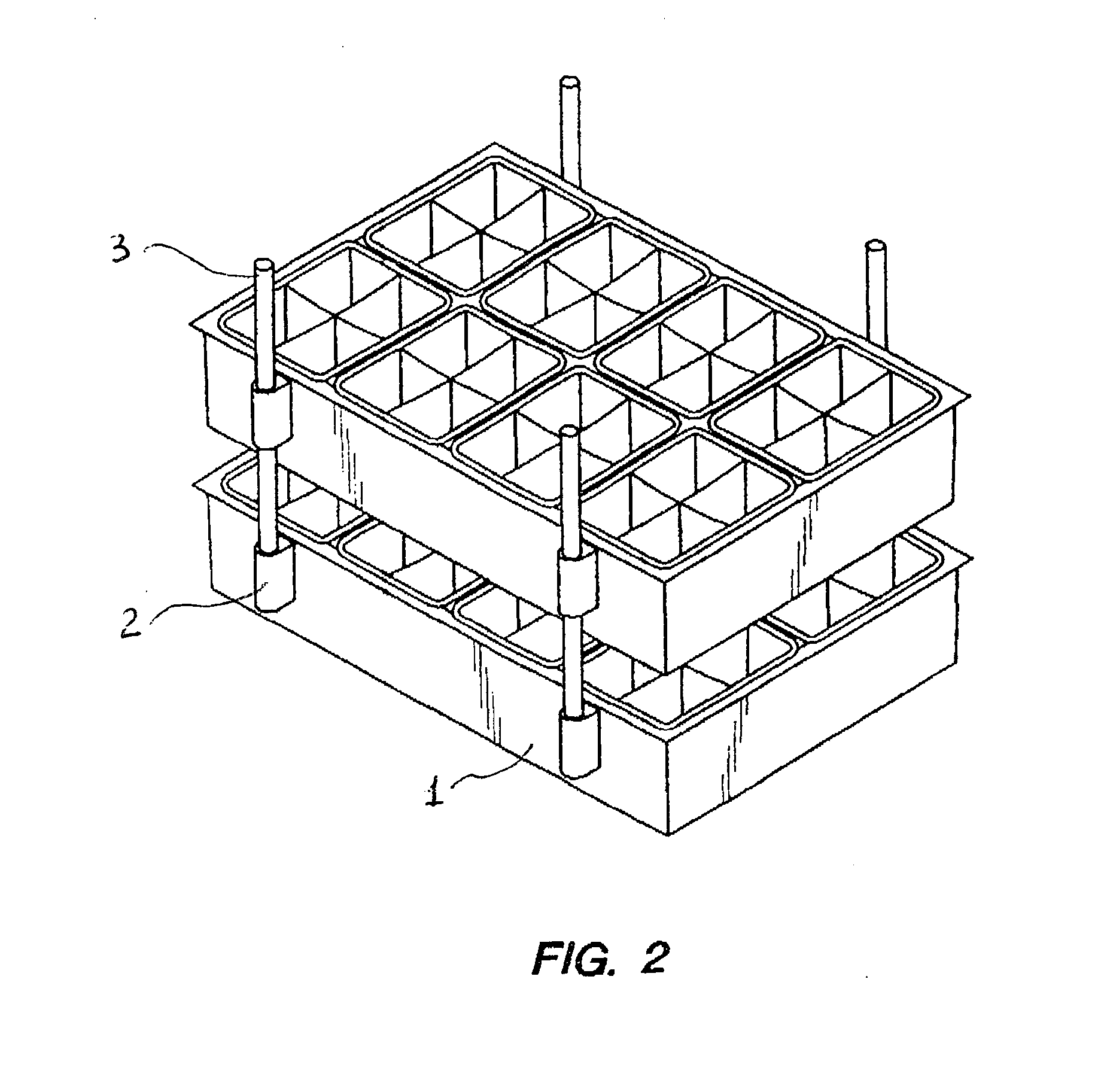
[0008]The present invention provides the following useful and novel features: it permits vertically stacking the nursery trays in an easy manner above each other in the storage or transportation position, allows for easy access to the cells contained in the trays and for safe growing the plants in the cells, and saves the plants during transportation due to arranging a predetermined vertical space between upper and lower trays.
[0009]The invention enables to quickly and simply assemble the trays into stacks, and dissemble them when needed. The inventive trays and means of their attachment can be merely made of suitable widely used materials applying known inexpensive technologies. The trays thus can be cheap and convenient for producers and users.
[0012]One of the aims of the inventive device is to make it simple for production. In order to provide simple manufacture of the trays, they should be designed uniformly, i.e. there should be no difference between a lower tray and an upper tray stacked above the lower tray.
[0014]The inventive device comprises cylindrical rods removably snug-fitting into the cavities of the bushings. The rods are preferably made identical, so that any rod can be used in place of another rod, which continues the uniformity of the bushings. Such uniformity enables interchangeability, and reduces expenses of the manufacturers, contributing to a decrease of price of the final product. In other embodiments, the bushings and rods may have a shape different from cylindrical, or may have additional conventional fasten means, fixing the rods inside the bushings.

Problems solved by technology

One of the typical problems with utilizing such trays is limited space where the trays are located.
All the aforementioned constructions and many others include complicated structures and elements, and hence are expensive and difficult to use.

Method used


Image

  • Stackable nursery trays for plants
  • Stackable nursery trays for plants
  • Stackable nursery trays for plants

Examples


Embodiment Construction

[0025]While the invention may be susceptible to embodiment in different forms, there are shown in the drawings, and will be described in detail herein, specific exemplary embodiments of the present invention, with the understanding that the present disclosure is to be considered an exemplification of the principles of the invention, and is not intended to limit the invention to that as illustrated and described herein.

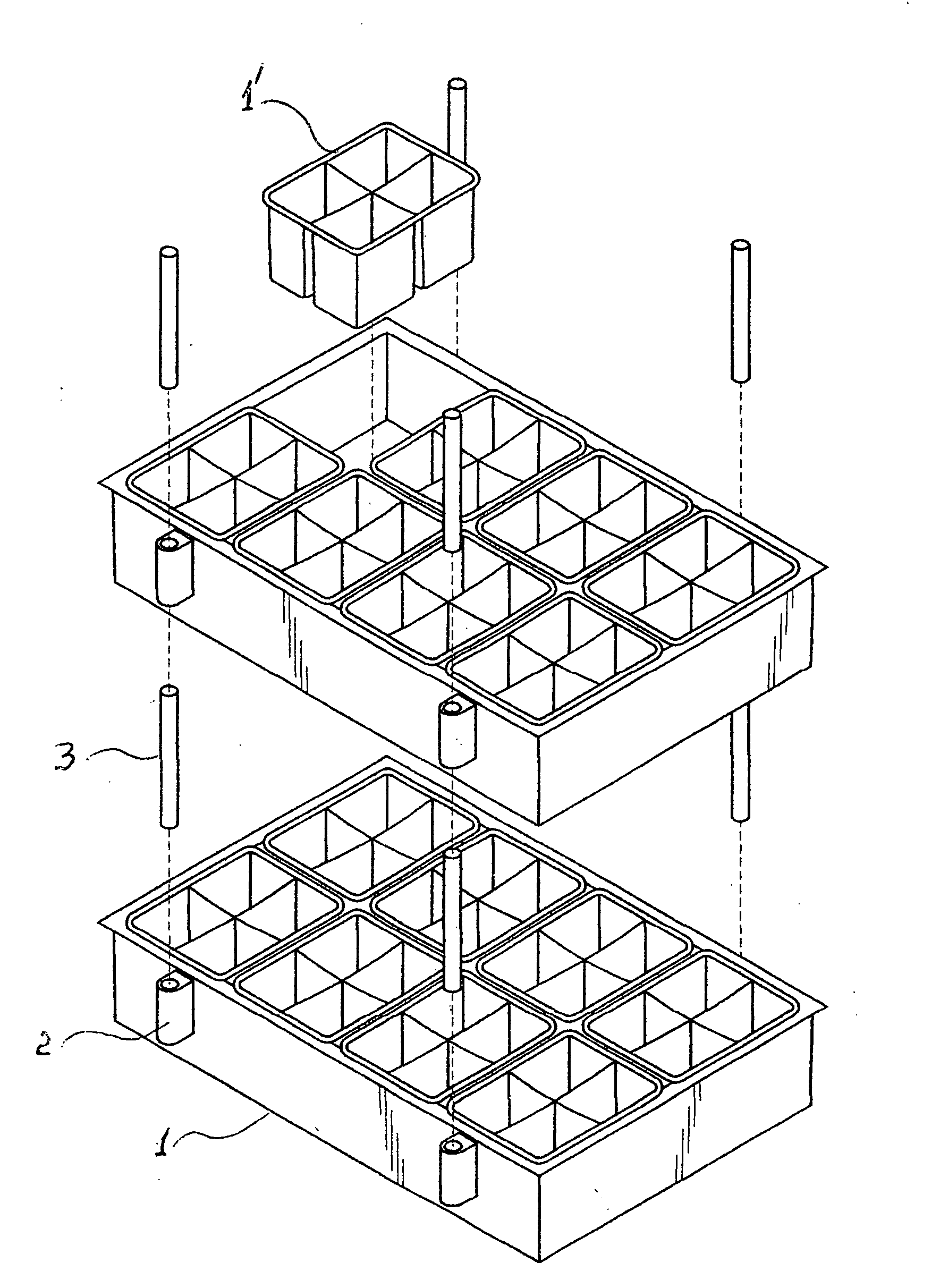
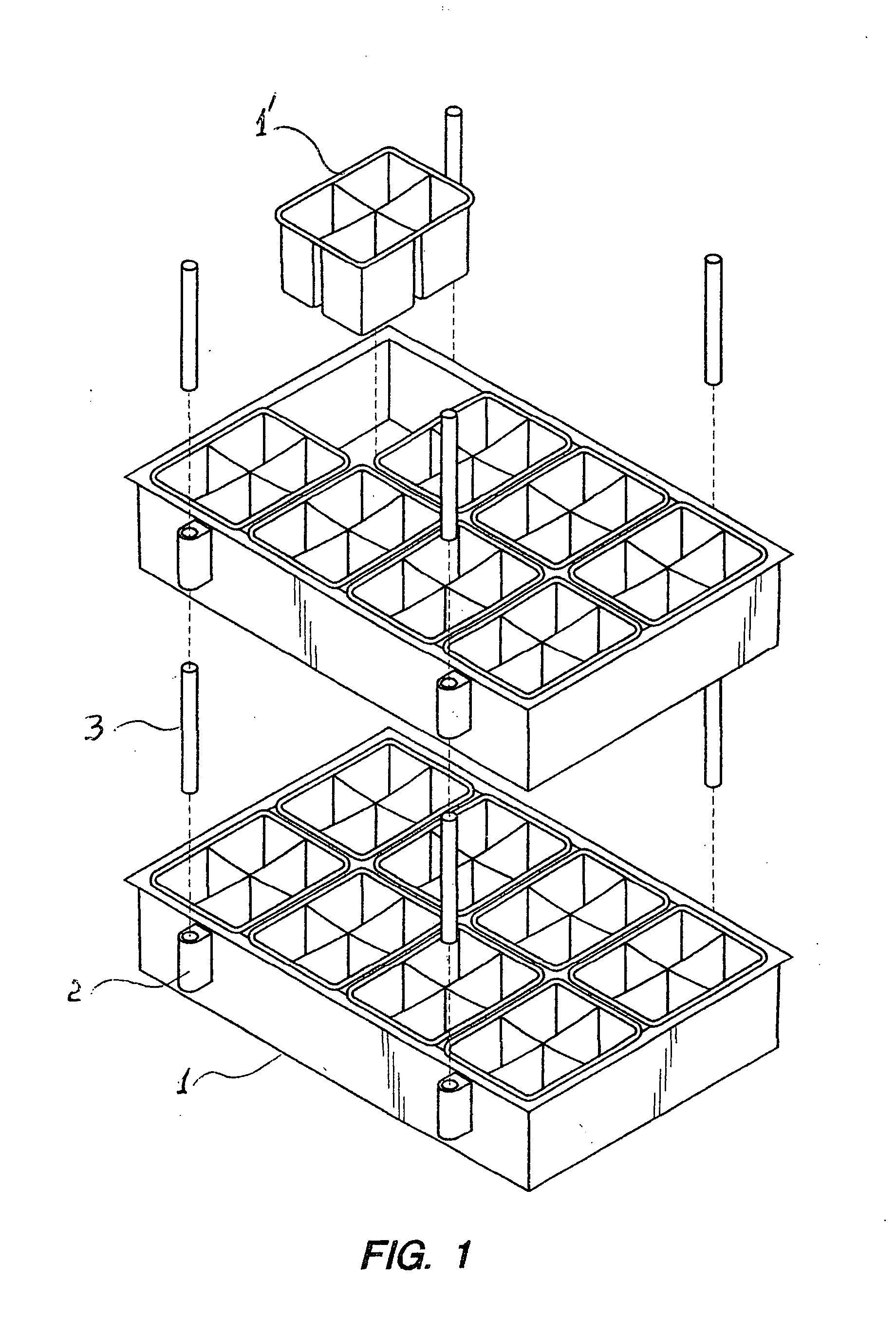
[0026]A preferred embodiment of the inventive device in a dissembled state is illustrated on FIG. 1, and comprises at least two identical trays (1), each made in a rectangular shape, and each containing a plurality of rectangular cells, such as a cell (1′) depicted separately, wherein growing plants can be placed. Each tray 1 includes a bottom and four vertical sidewalls fixed to the bottom.

[0027]The device comprises a plurality of bushings (2), externally shown on FIGS. 1, 2, and 3, which bushings 2 are outwardly coupled to the sidewalls of each tray 1, so that each o...


PUM


Abstract

A simple and inexpensive nursery device is provided, comprising: at least two identical trays containing plant cells, identical bushings coupled to the trays so that each of the trays furnished with an equal number of the bushings identically disposed at corresponding predetermined points of the trays, and identical rods of a predetermined height. Bushings internally include upper and lower cavities, and partitions fixed therebetween. The rods are made insertable into the cavities, being supported by the partitions. The trays can be assembled in stack by making one tray a lower tray, inserting the rods into the lower tray's upper cavities, inserting the rods into the lower cavities of the corresponding bushings of another tray, thereby making it an upper tray. Embodiments include different bushings dispositions on the trays, combined rods assembled of component rods. Some rods include threaded top holes and threaded bottom heads, some bushings cavities include fixation threadings.

Description

FIELD OF THE INVENTION[0001]The invention relates to devices usable for growing plants, such as flowers, vegetables, etc. More specifically, it relates to nursery trays, mostly containing cells, which cells are used for growing plants, though may find other useful applications.BACKGROUND OF THE INVENTION[0002]There are known several constructions of trays for plants in the prior art. One of the typical problems with utilizing such trays is limited space where the trays are located. A common solution to the problem is arranging the trays in stacks, i.e. above each other.[0003]One such example is described in U.S. Pat. No. 5,040,328: “A mushroom tray comprising a tray portion having opposing sidewalls, opposing end walls and a substantially flat bottom sheet having a parallity of channels formed therein and extending therealong, corrosion-resistant I-beams positioned within the channels for strengthening and stiffening the bottom sheet, and a parallity of clips for securing the I-beam...

Claims


Application Information

Patent Timeline
IPC IPC(8): A01G9/02
CPCA01G9/104A01G9/028A01G9/0295
Inventor INGRASSIA, JOHN
Owner INGRASSIA JOHN
Learn More