
Integrated arrangement structure of decanter centrifuge and hydraulic station

A decanter centrifuge and configuration structure technology, which is applied in the field of machinery, can solve problems such as inconvenient operation, long pipelines, and large space occupation, and achieve smooth oil return

Inactive Publication Date: 2011-09-21
SHANGHAI CENTRIFUGE INST
View PDF6 Cites 2 Cited by
  • Summary
  • Abstract
  • Description
  • Claims
  • Application Information

AI Technical Summary

Problems solved by technology

The operation of the decanter centrifuge requires oil inlet and oil return. Since the pressure and flow of the two oils are different, the oil inlet and oil return in the prior art are provided by two pumps of the hydraulic station separately configured elsewhere, so The result of the structure is that the mechanism is bulky, the pipeline is long, the operation is inconvenient, it occupies a large space, and the amount of transportation and movement is large. Therefore, it is hoped that there will be an improvement plan

Method used


Image

  • Integrated arrangement structure of decanter centrifuge and hydraulic station
  • Integrated arrangement structure of decanter centrifuge and hydraulic station
  • Integrated arrangement structure of decanter centrifuge and hydraulic station

Examples


Embodiment Construction

[0025] The structure of the present invention will be described in further detail below in conjunction with the drawings.

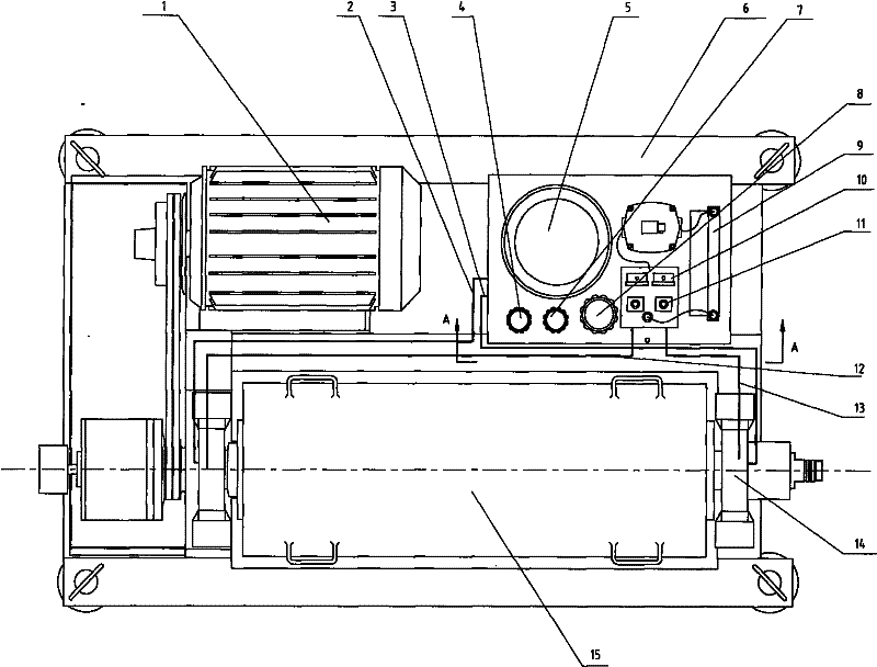
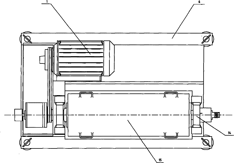
[0026] The integrated configuration structure of the decanter centrifuge and the hydraulic station. In the rectangular frame 6, one side is a horizontally arranged decanter centrifuge cylinder 15, and the other end is equipped with a motor 1, which is sent to the centrifuge through a belt The input shaft end of the barrel 15 is equipped with a hydraulic station in the rear space of the electric motor 1.

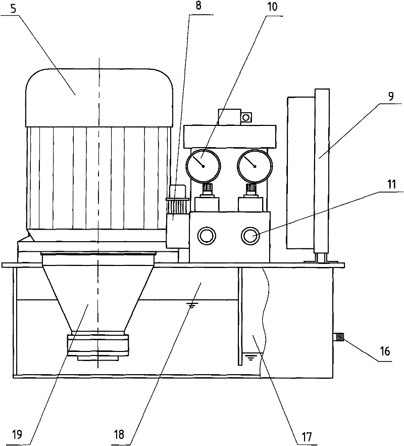
[0027] The hydraulic station is a vertically arranged rectangular body. The oil pump motor 5 drives the oil pump 19, and the oil pump 19 is connected to the two sides of the centrifuge cylinder 15 by the front and rear oil inlet pipes 12 and 13 through the two oil inlet speed regulating valves 11. At the end, the oil supply tank 18 and the oil return tank 17 are arranged side by side at the lower part, and the lower parts of the two oil tanks are communicated...


PUM


Abstract

The invention relates to a centrifuge structure in the field of machines, in particular to an integrated arrangement structure of a decanter centrifuge and a hydraulic station. In a rectangular frame (6), one side is provided with an accumbent decanter centrifuge barrel (15), the end of the other side is provided with a motor (1), and power is transmitted to the input shaft end of the centrifuge barrel (15) through a belt. The structure is characterized in that: the hydraulic station is arranged in a rear space of the motor (1) and is a vertically arranged rectangular body; an oil pump motor (5) drives an oil pump (19); the oil pump (19) is respectively connected to the two ends of the centrifuge barrel (15) by front and rear oil inlet pipes (12 and 13) through two oil inlet speed regulating valves (11); an oil supply box (18) and an oil return box (17) are parallelly arranged on the lower part; the lower parts of the two oil boxes are communicated with each other; and the upper part of the oil supply box (18) is connected with a vacuum pump (8). Through the technical scheme, the residual space on the frame (6) is fully utilized, so that the space of a factory building is saved, the problem of transportation and installation inconvenience of a split structure is solved, engineering progress is accelerated, and efficiency is improved.

Description

Technical field [0001] The invention relates to a centrifuge structure in the mechanical field, and specifically relates to an improved configuration structure of a decanter centrifuge. Background technique [0002] Centrifuge is a machine that uses centrifugal force to separate liquid and solid particles or each component in a mixture of liquid and liquid. [0003] The centrifuge is mainly used to separate the solid particles in the suspension from the liquid. The solid particles of different density or size are used to settle in the liquid at different speeds. Some sedimentation centrifuges can also classify the solid particles according to density or particle size. [0004] Centrifuge is widely used in chemical, petroleum, food, pharmaceutical, mineral processing, coal, water treatment and shipbuilding sectors. [0005] The centrifuge has a cylinder that rotates at high speed around its axis, called a drum, which is usually driven by a motor. After the suspension is added to the r...

Claims


Application Information

Patent Timeline
Patent Type & Authority Applications(China)
IPC IPC(8): B04B1/00B04B15/00
Inventor 徐群曲世强钱青
Owner SHANGHAI CENTRIFUGE INST
Learn More