Power transmitting system for rotary wings of automatic revolving door

a technology of power transmission system and rotary wing, which is applied in the direction of wing operation mechanism, door/window fitting, construction, etc., can solve the problems of preventing safety problems, unable to obtain a desire for a wider passage, and unable to catch things or parts of clothes, so as to improve structural stability, simplify the driving means, and prevent safety problems

Inactive Publication Date: 2009-05-14
WANG BOK KWON
View PDF7 Cites 8 Cited by
  • Summary
  • Abstract
  • Description
  • Claims
  • Application Information

AI Technical Summary

Benefits of technology

[0016]It is another object of the present invention to provide a rotation driving force structure of a revolving wing for an automatic revolving door having a dispersion unfolding structure in which a protrusion is formed at an inner side of an outer body of an automatic revolving door, and a plurality of rotation rollers engaged at an outer surface of the inner body are supported by the protrusion, and a driving force is applied to from the rotation motor engaged at an inner side of the inner body to one of the rotation rollers, so that the rotation roller operates a role of the driving roller so that the rotation roller rotates the inner body and ...

Problems solved by technology

In particular, the conventional revolving door and automatic revolving door have problems that a thing or part of clothes may be caught by the end of the revolving wing or the inner surface of the transparent wall member.
Even when the revolving wing is folded, since the revolving wing and the center rotary shaft still remain at the center of the revolving door, it is impossible to obtain a wider passage.
Therefore, since the center rotary shaft and revolving wing still remain at the inner center of the revolving door, it is impossible to obtain a desire wider passage.
In case of a VIP or entertainment star who needs body guards, since he should pass the revolving door alone, a security problem occurs since his body is exposed without security.
In addition, in a place where exhibits a large thing like in a vehicle exhibition place or a furniture exhibition plac...

Method used


Image

  • Power transmitting system for rotary wings of automatic revolving door
  • Power transmitting system for rotary wings of automatic revolving door
  • Power transmitting system for rotary wings of automatic revolving door

Examples


Embodiment Construction

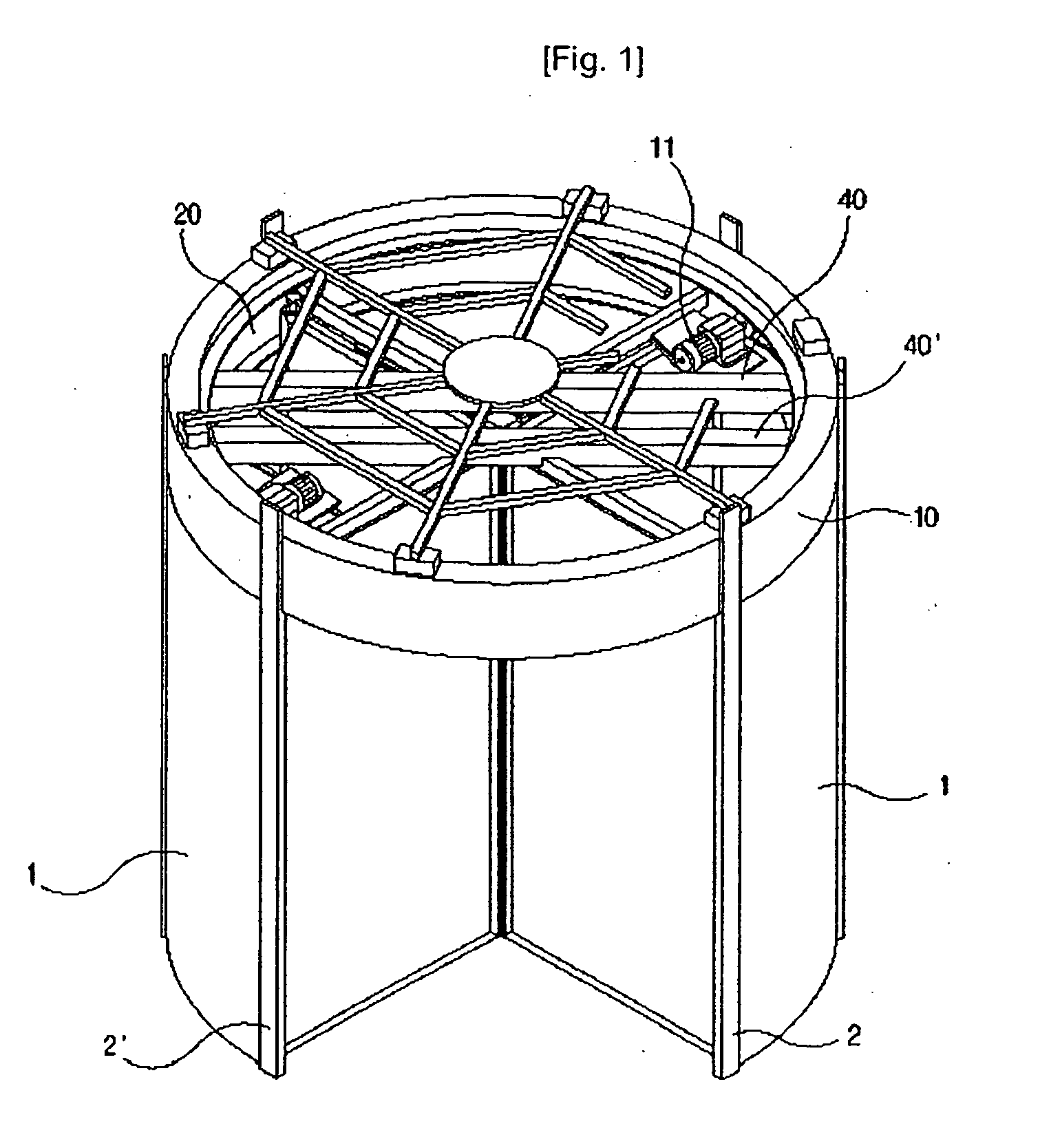
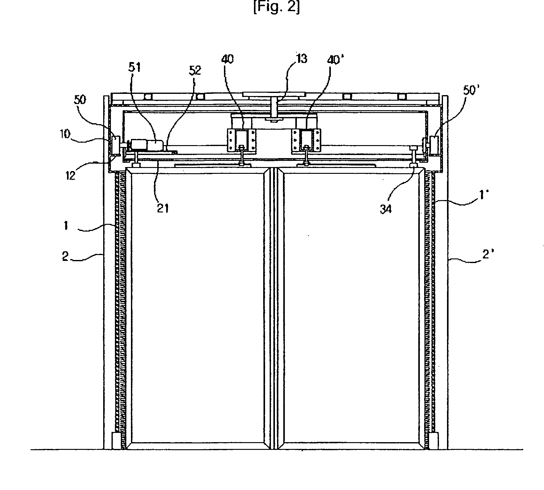
[0022]FIG. 1 is a perspective view illustrating an automatic revolving door having a revolving driving force structure according to the present invention, and FIG. 2 is a side cross sectional view illustrating an automatic revolving door according to the present invention.

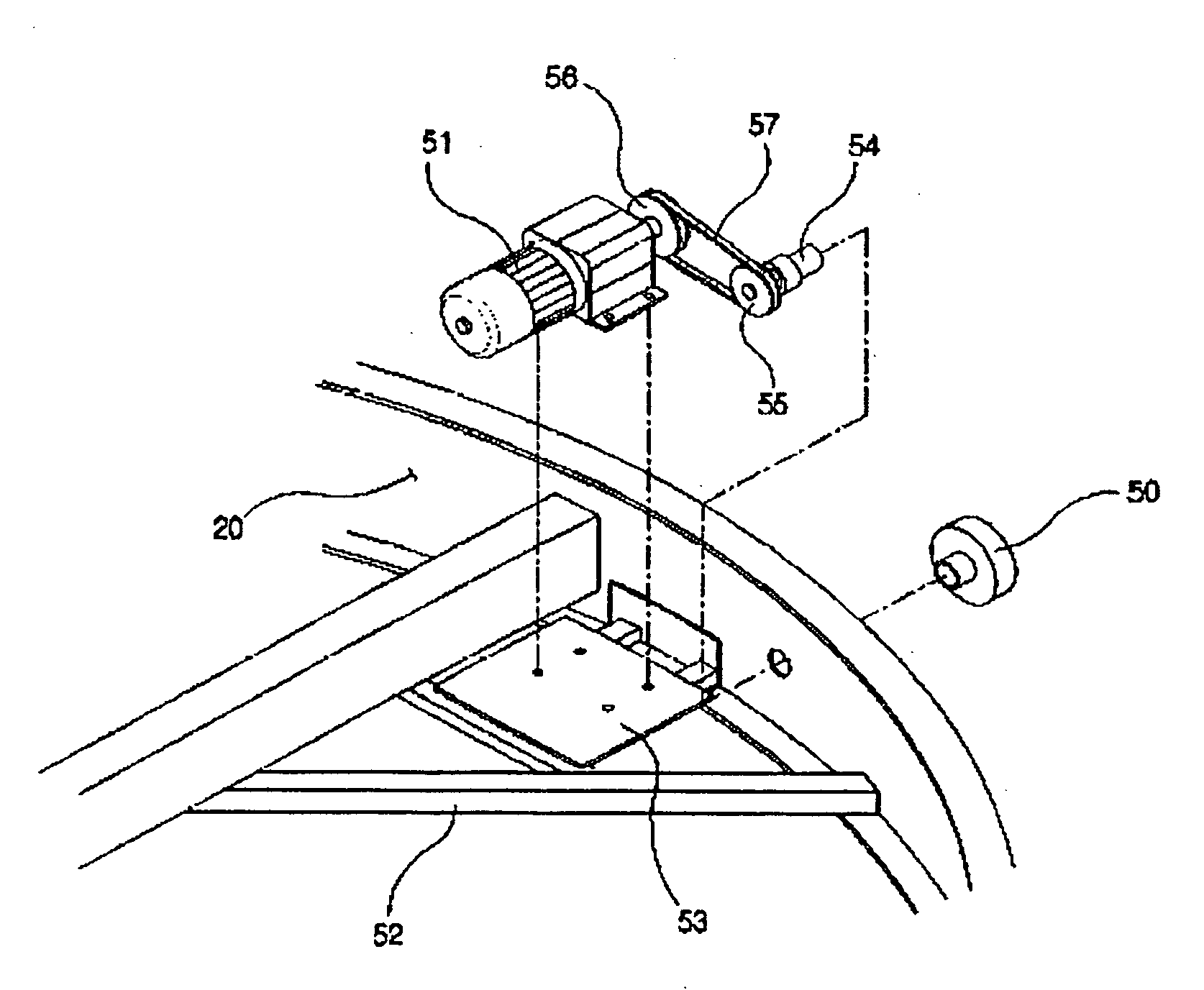
[0023]In an automatic folding structure of a revolving wing for an automatic revolving door in which an inner body 20 having an upper plate 21 at a lower side of the same is provided at an inner side of an outer body 10 formed at an upper side of vertical frames 2 and 2′ having transparent wall members 1 and 1′, and a plurality of divided revolving wings 30 and 30′ are provided at the lower side of the upper plate 21, so that the inner body 20 and the revolving wings 30 and 30′ rotate together, and the revolving wings 30 and 30′ are fully unfolded in the direction of the transparent wall members 1 and 1′ along the crossbars 40 and 40′ with respect to a hinge shaft 34 of one upper side, there is provided an improved...


PUM


Abstract

A revolving driving force structure of a revolving wing for an automatic revolving door is provided, in which a revolving door of an automatic revolving door having an inner body with a revolving door at an inner side of an outer body provided at a front end of a transparent wall member is generated based on a rotation roller protruded from the inner body and by an operation motor which rotates the rotation door, and the rotation roller is supported on an inner support protrusion, and it is possible to prevent any safety accident based on a stable rotation of the inner body and the revolving wing and a constant gap during the rotation of the revolving wing, and a simple structure can be obtained, and a durability and life span increase without any load.

Description

TECHNICAL FIELD[0001]The present invention relates to a revolving driving force structure of a revolving wing for an automatic revolving door installed at an entrance of each building, and in particular to a revolving driving force structure of a revolving wing for an automatic revolving door in which a revolving door of an automatic revolving door having an inner body with a revolving door at an inner side of an outer body provided at a front end of a transparent wall member is generated based on a rotation roller protruded from the inner body and by an operation motor which rotates the rotation door, and the rotation roller is supported on an inner support protrusion, and it is possible to prevent any safety accident based on a stable rotation of the inner body and the revolving wing and a constant gap during the rotation of the revolving wing, and a simple structure can be obtained, and a durability and life span increase without any load.BACKGROUND ART[0002]Generally, a revolvin...

Claims


Application Information

Patent Timeline
IPC IPC(8): E05D15/02
CPCE05Y2201/434E05Y2800/21E05Y2900/132E05F15/611E05F15/605E05F15/608E05Y2600/46E05D15/48E05D15/02
Inventor WANG, BOK KWON
Owner WANG BOK KWON
Why Eureka
Try Eureka