This helps you quickly interpret patents by identifying the three key elements:
Problems solved by technology
Method used
Benefits of technology
Benefits of technology
[0032]According to the present invention constituted as described above, the press-forming device and the press-forming method which are capable of controlling a tool strain at the time of press-forming and have high accuracy and high applicability can be provided.
Problems solved by technology
Occurrence of a tool strain reduces the dimensional accuracy of a formed product.
Therefore, the tool strain changes due to change of the various conditions such as the press machine, tool shape, quality of the material to be worked, shape of the material to be worked, lubrication and stamping force, and the change of the tool strain causes quality scatter between the stamp parts.
In the forming prediction by the finite element method or the like cannot take the tool strain into consideration due to the calculation ability and the like, and therefore, the tool strain makes the prediction of forming by the finite element method difficult.
Further, in forming with the tool having a complicated shape, the contact pressure distribution acting on the tool is not uniform, and the strain amount distribution occurring to the tool is complicated.
Therefore, in the constitution of the invention of Patent Document 1, the actuator control for controlling the strain control amount to the desired amount is difficult.
Therefore, when the invention of Patent Document 1 is applied to draw forming, the measured tool strain amount differs from the tool strain amount during forming, and control accuracy becomes worse.
Method used
Image
Click on the blue label to locate the original text in one second.
Reading with bidirectional positioning of images and text.
Examples
first embodiment
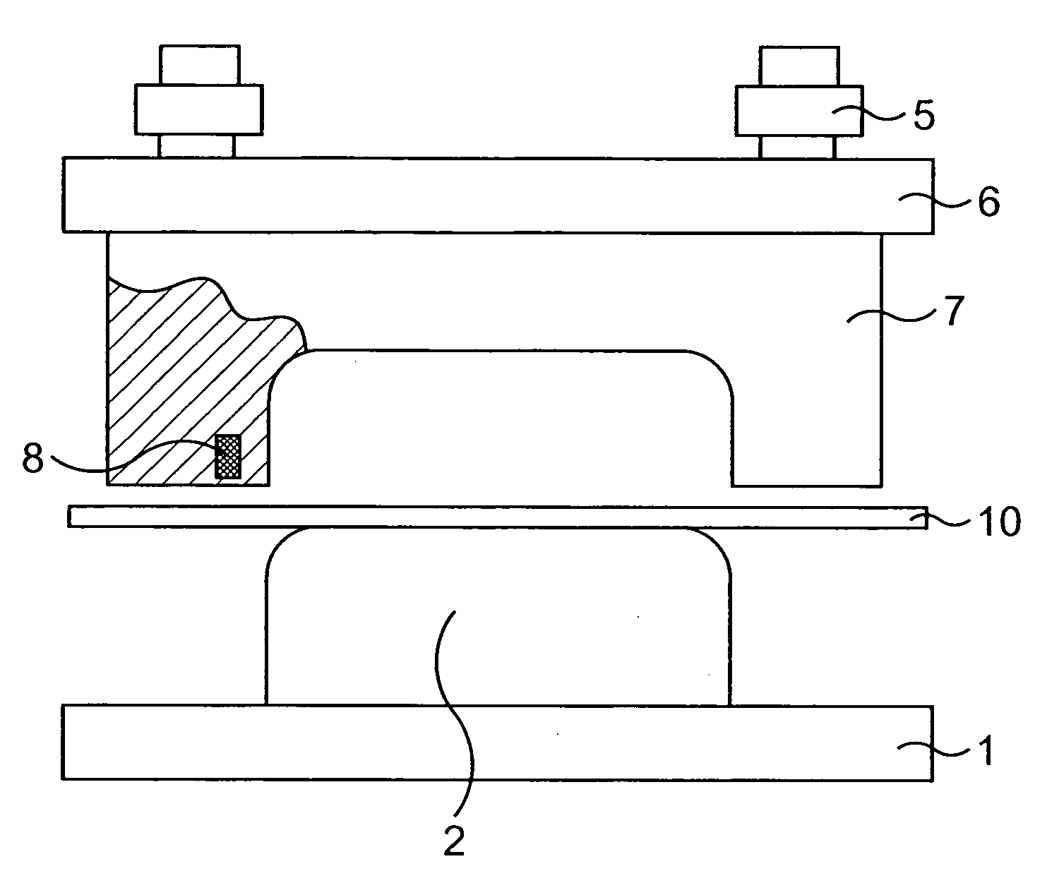
[0061]FIG. 1 shows a schematic view of an example of a press-forming device of a first embodiment. A punch 2 is mounted on a press machine bolster 1, and a die 7 is mounted to an upper slide 6 which is driven by a forming load / speed regulating means 5 respectively. Reference numeral 10 in the drawing denotes a thin plate that is a material to be worked.
[0062]In FIG. 1, the die 7 is selected as a member to be controlled, and a strain amount measuring means 8 is installed in it.
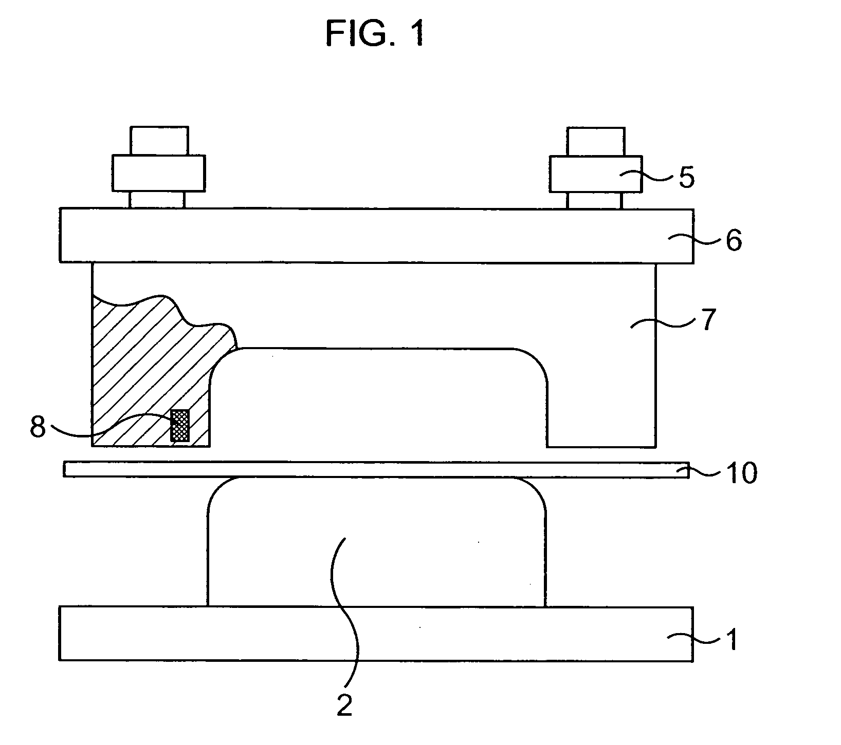
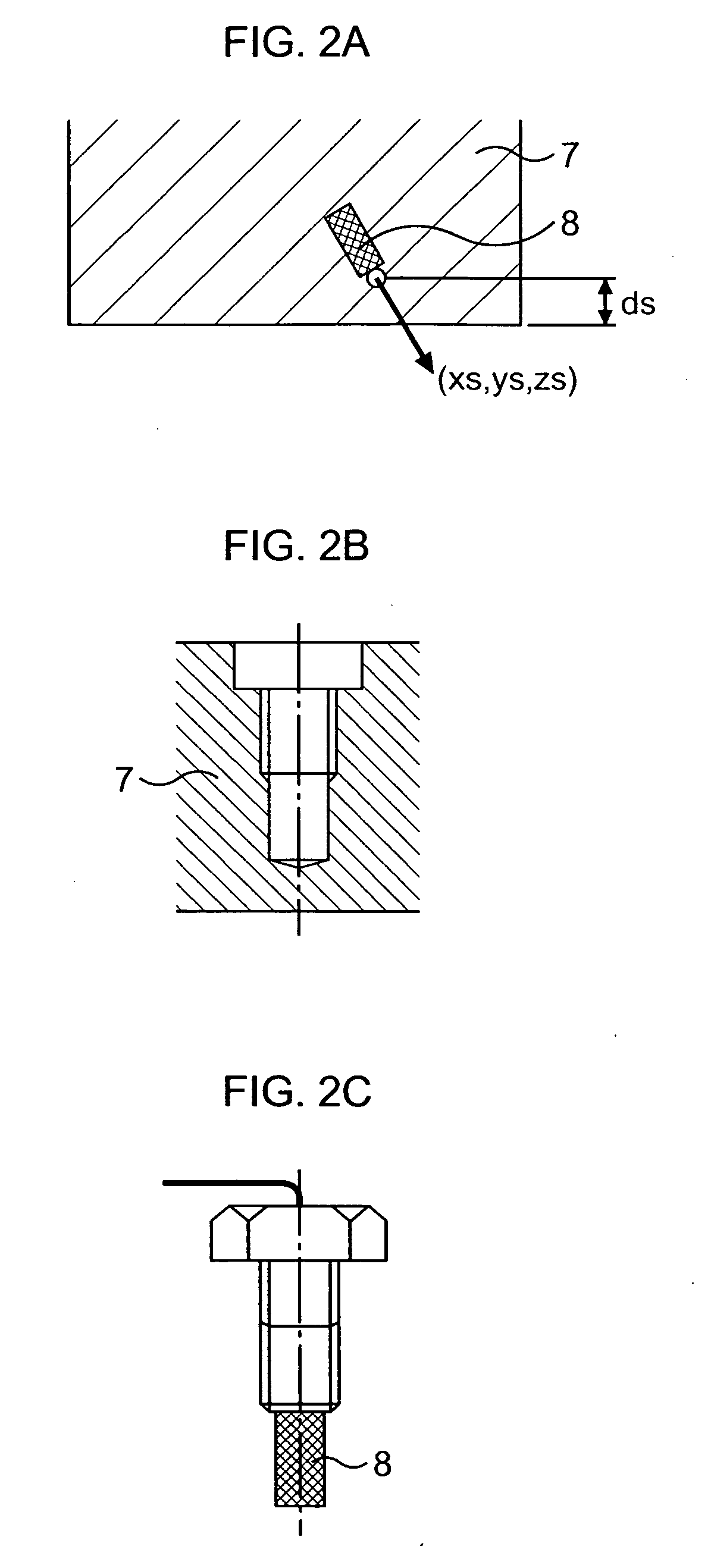
[0063]FIG. 2A shows an enlarged area in the vicinity of the installation location of the strain amount measuring means 8. As one example of the installation method of the strain amount measuring means 8, a drill hole which does not penetrate through the die 7 is bored in the die 7 and a female thread screw is cut in the hole as shown in a schematic view of FIG. 2B, the strain measuring means 8 shown in FIG. 2C is placed in the bottom of the drill hole, and an axial force is applied with a plug to press-fit it t...
second embodiment
[0070]FIG. 6 shows a schematic view of an example of a press-forming device of a second embodiment. The punch 2 is mounted on the press machine bolster 1, the blank holder 4 is mounted to the blank holding force regulating means 3, and the die 7 is mounted to the upper slide 6 which is driven by the tool load / speed regulating means 5.
[0071]In FIG. 6, three of the die 7, the punch 2 and the blank holder 4 are selected as the members to be controlled, and the strain amount measuring means 8 are installed in their respective inner parts. At least any one of the die 7, the punch 2 and the blank holder 4 needs to be selected as the member to be controlled.
third embodiment
[0072]FIG. 7 shows a schematic view of an example of a press-forming device of a third embodiment. As in FIG. 6, the punch 2 is mounted on the press machine bolster 1, the blank holder 4 is mounted to the blank holding force regulating means 3, and the die 7 is mounted to the upper slide 6 which is driven by the tool load / speed regulating means 5.
[0073]In FIG. 7, three of the die 7, the punch 2 and the blank holder 4 are selected as the members to be controlled, and the strain amount measuring means 8 and strain amount control means 9 are installed in their respective inner parts.
[0074]FIG. 8 shows the details of the installation situation of the strain amount measuring means 8 and the strain amount control means 9 in FIG. 7. The installation method of the strain amount measuring means 8 is the same as described with FIGS. 2A to 2C. As the installation method of the strain amount control means 9, there is also a method for boring a drill hole which does not penetrate through and pre...
PUM
Property
Measurement
Unit
Fraction
aaaaa
aaaaa
Fraction
aaaaa
aaaaa
Fraction
aaaaa
aaaaa
Abstract
A press-forming device has a punch (2), a die (7) which relatively moves with respect to the punch (2), a strain amount measuring means (8) which is provided inside a member to be controlled and measures a strain amount of the aforesaid member to be controlled which occurs in accordance with press-forming, when at least one of the punch (2) and the die (7) is made the aforesaid member to be controlled, and a strain amount control means (9) which is provided in the aforesaid member to be controlled and controls the strain amount of the aforesaid member to be controlled which occurs in accordance with press-forming. The strain amount control means (9) controls a drive amount of the aforesaid member to be controlled so that the strain amount measured by the strain amount measuring means (8) is in a predetermined range during forming. Thereby, reduction in a surface strain, improvement in shape fixability or the like of a press formed product can be achieved.
Description
TECHNICAL FIELD[0001]The present invention relates to a press-forming device and a press-forming method of, for example, a thin plate, and particularly relates to a press-forming device and a press-forming method which measure a strain of a tool occurring at the time of press working.BACKGROUND ART[0002]At the time of press working, a stamping force by a press machine, a reaction force of the material to be worked deformation reaction and the like act on a tool and the tool elastically deforms. Such elastic deformation is called a strain of the tool.[0003]FIG. 25 shows a conceptual view of the tool strain occurring at the time of press-forming in a press machine constituted of a punch 2, a die 7 and a blank holder 4. The solid line shows the outer shape of the tool before press-forming, and the dotted line shows the outer shape of the tool when the tool elastically deforms at the time of press-forming. FIG. 25 shows the deformation with emphasis, but the elastic deformation amount i...
Claims
Application Information
Patent Timeline
Application Date:The date an application was filed.
Publication Date:The date a patent or application was officially published.
First Publication Date:The earliest publication date of a patent with the same application number.
Issue Date:Publication date of the patent grant document.
PCT Entry Date:The Entry date of PCT National Phase.
Estimated Expiry Date:The statutory expiry date of a patent right according to the Patent Law, and it is the longest term of protection that the patent right can achieve without the termination of the patent right due to other reasons(Term extension factor has been taken into account ).
Invalid Date:Actual expiry date is based on effective date or publication date of legal transaction data of invalid patent.
IPC IPC(8): B21D43/00B21D22/00
CPCB21D22/20B21D37/00B21D22/22B21D22/02
InventorKUWAYAMA, TAKUYASUZUKI, NORIYUKIDUROUX, PATRICK

