Elevator arrangement

Inactive Publication Date: 2009-05-14
KONE CORP
View PDF12 Cites 38 Cited by
  • Summary
  • Abstract
  • Description
  • Claims
  • Application Information

AI Technical Summary

Benefits of technology

[0007]An elevator system utilizing the arrangement according to the invention is more operationally reliable and safer for passengers than prior art. By means of the arrangement according to the invention a malfunction of the processor and/or an electromagnetic pulse connected to the system, which short-circuits the transistors, disconnects the power supply from the loads to be controlled and a dangerous situation does not occur. Further by means of the invention it is also possible to detect a short-circuit of the load or the lack of a load. By means of the invention it is also possible to implement an elevator system, in which noise drawbacks caused by the contactors are less than prior art.
[0008]The arrangement of the invention for controlling the power supply of the loads of an elevator system is characterized by what is disclosed in the characterization part of claim 1. The method according to the invention for controlling the power supply of the loads in an elevator system is characterized by what is disclosed in the characterization part of claim 9.
[0009]Other embodiments of the invention are characterized by what is disclosed in the other claims. Some inventive embodiments are also discussed in the descriptive section of the present application. The inventive content of the application can also be defined differently than in the claims presented below. The inventive content may also consist of several separate inventions, especially if the invention is considered in the light of expressions or implicit sub-tasks or from the point of view of advantages or categories of advantages achieved. In this case, some of the

Problems solved by technology

The electromechanical contactors, by means of which the electricity supply of the electricity supply appliance and of the brakes of the elevator are controlled, are however susceptible to switching interference, which can lead to a dangerous situation.
Furthermore the contactors are wearing devices, the operating life of which is limited

Method used


Image

  • Elevator arrangement
  • Elevator arrangement
  • Elevator arrangement

Examples


Embodiment Construction

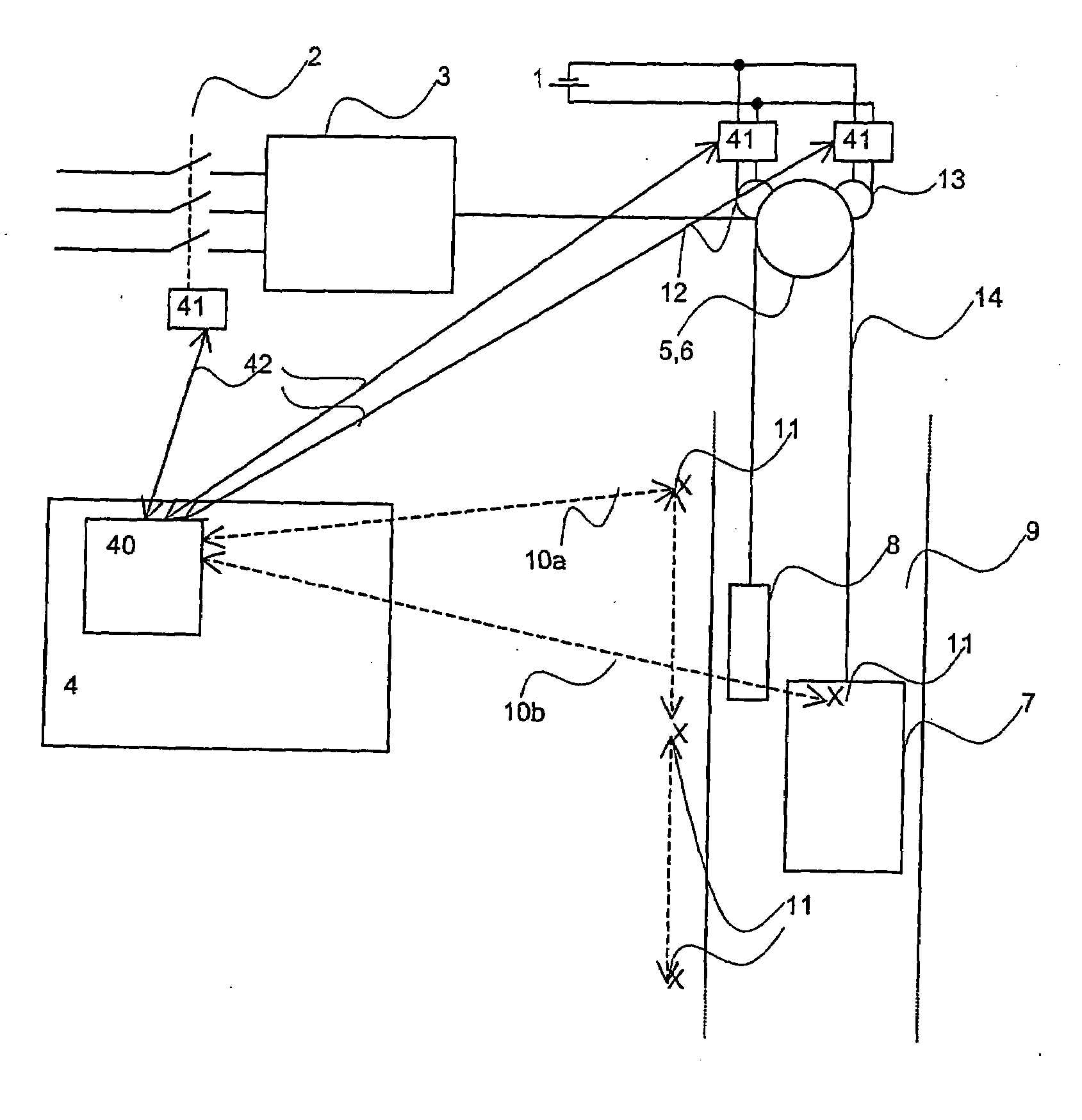
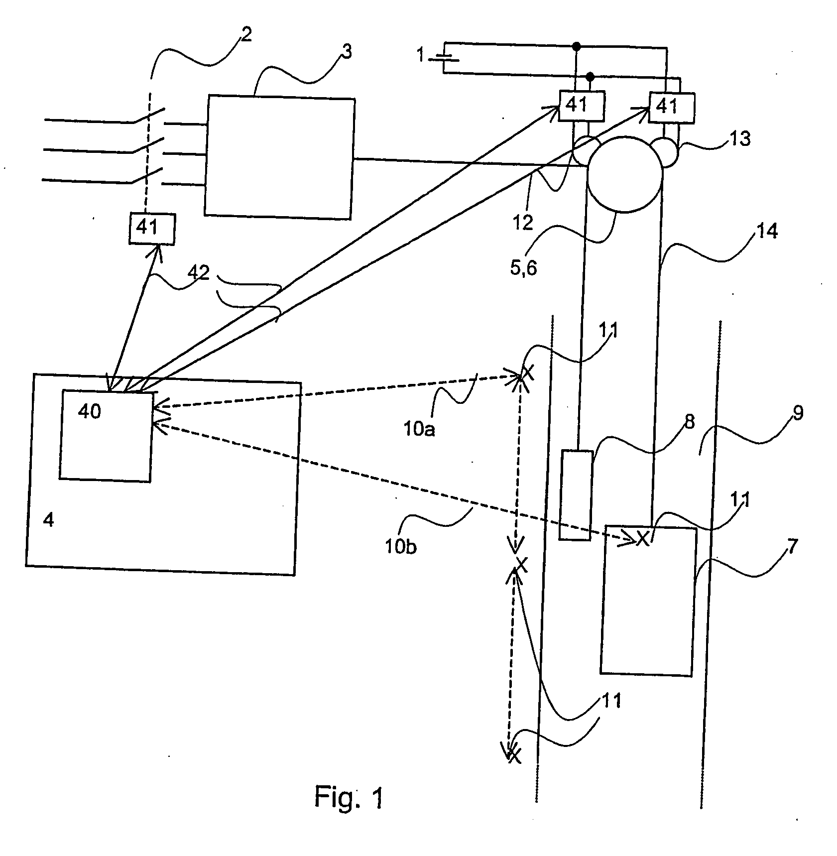
[0022]FIG. 1 presents an elevator system, in which the arrangement of the invention for controlling the power supply of the loads of an elevator system is applied. In the elevator system according to FIG. 1 the elevator car 7 and the counterweight 8 can be moved in the elevator shaft 9 by means of the elevator roping 14 by rotating the traction sheave 6 connected to or integrated into the elevator motor 5. The electricity supply and control of the elevator motor occur by means of a frequency converter 3. Between the frequency converter 3 and the electricity network is an elevator contactor 2. The elevator system further comprises a safety circuit 10, by means of which it is checked that, among other things, the doors of the shaft 9 and of the elevator car 7 are closed and that other requirements for safe elevator travel are fulfilled before the elevator starts moving. The safety circuit 10 can be implemented in different ways, although the criterion is that information about the clo...


PUM


Abstract

The present invention discloses an arrangement and a method for controlling the power supply of the load of an elevator system. The arrangement comprises at least a monitoring unit (40) and at least one controllable power source (41), which controllable power source (41) is fitted between the load (2, 12, 13) of the elevator system and the monitoring unit (40) such that the power supply of the load (2, 12, 13) of the elevator system can be controlled by means of a control signal transmitted to the controllable power source (41) by the monitoring unit (40). The monitoring unit (40) according to the invention contains at least one input for determining the status of at least one safety switch (11) of the elevator system. On the basis of the status of the safety switch a control signal (47) either comprised of pulses or in a static state is sent with the monitoring unit (40) to at least one controllable power source (41).

Description

FIELD OF THE INVENTION[0001]The present invention relates to an arrangement for controlling the power supply of a load of an elevator system as defined in the preamble of claim 1 and a method for controlling the power supply of a load in an elevator system as defined in the preamble of claim 9.BACKGROUND OF THE INVENTION[0002]In elevator systems, movement of the elevator car is permitted only when the doors of the elevator car and of the shaft are closed and the other conditions required to ensure the safety of passengers are fulfilled. In elevator systems in which the electric motor that moves the elevator car is controlled by means of a frequency converter according to the commands of the control unit of the elevator, safety is typically ensured with a safety circuit. The safety circuit can be implemented e.g. such that switches, which are connected to each other in series, are placed in the points that are essential from the standpoint of safety. The electricity supply of the ele...

Claims


Application Information

Patent Timeline
IPC IPC(8): B66B1/00
CPCB66B5/0031B66B1/30B66B5/02
Inventor SYRMAN, TIMOKATTAINEN, ARI
Owner KONE CORP
Why Eureka
Try Eureka