Valve assembly having a reinforced valve seat

a valve assembly and valve seat technology, applied in the direction of valve details, valve arrangements, valve housings, etc., can solve the problems of process media leaking into the valve housing, and the use of injectable packing does not provide a rigid valve sea

Active Publication Date: 2009-05-14
EMERSON VULCAN HLDG LLC
View PDF12 Cites 17 Cited by
  • Summary
  • Abstract
  • Description
  • Claims
  • Application Information

AI Technical Summary

Benefits of technology

[0004]Preferred embodiments of the inventions are directed to a knife gate valve having a valve body defined by a first and second body halves. The valve halves are assembled to define a flow path, a knife gate channel and a seat channel. A knife gate is disposed between the body halves and adapted to traverse the gate channel. The knife gate is configured to be in an open position to allow process flow through said valve and a closed position to prevent process flow through the valve. The knif

Problems solved by technology

This movement with the recesses of the valve body causes process media to leak into the valve housing.
However, use of in

Method used


Image

  • Valve assembly having a reinforced valve seat
  • Valve assembly having a reinforced valve seat
  • Valve assembly having a reinforced valve seat

Examples


Embodiment Construction

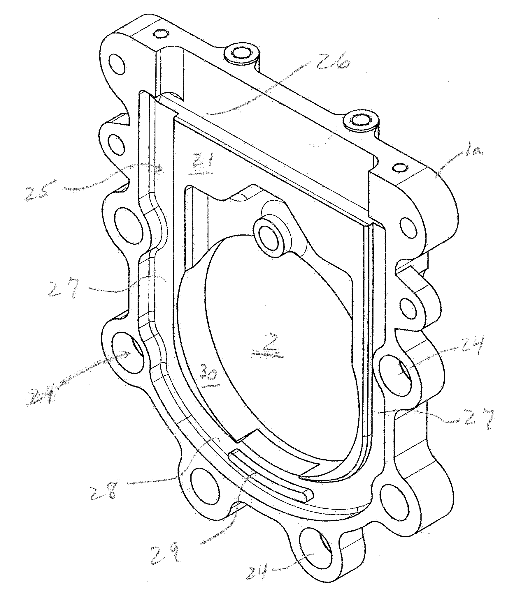
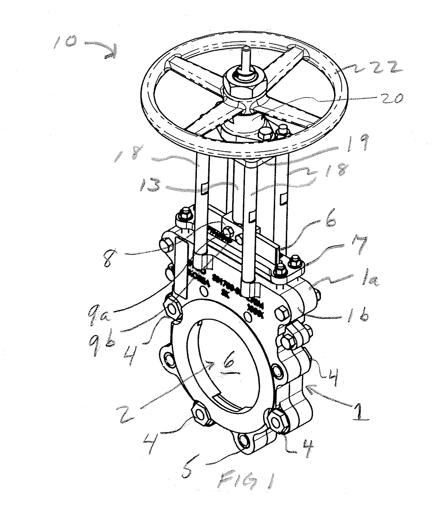
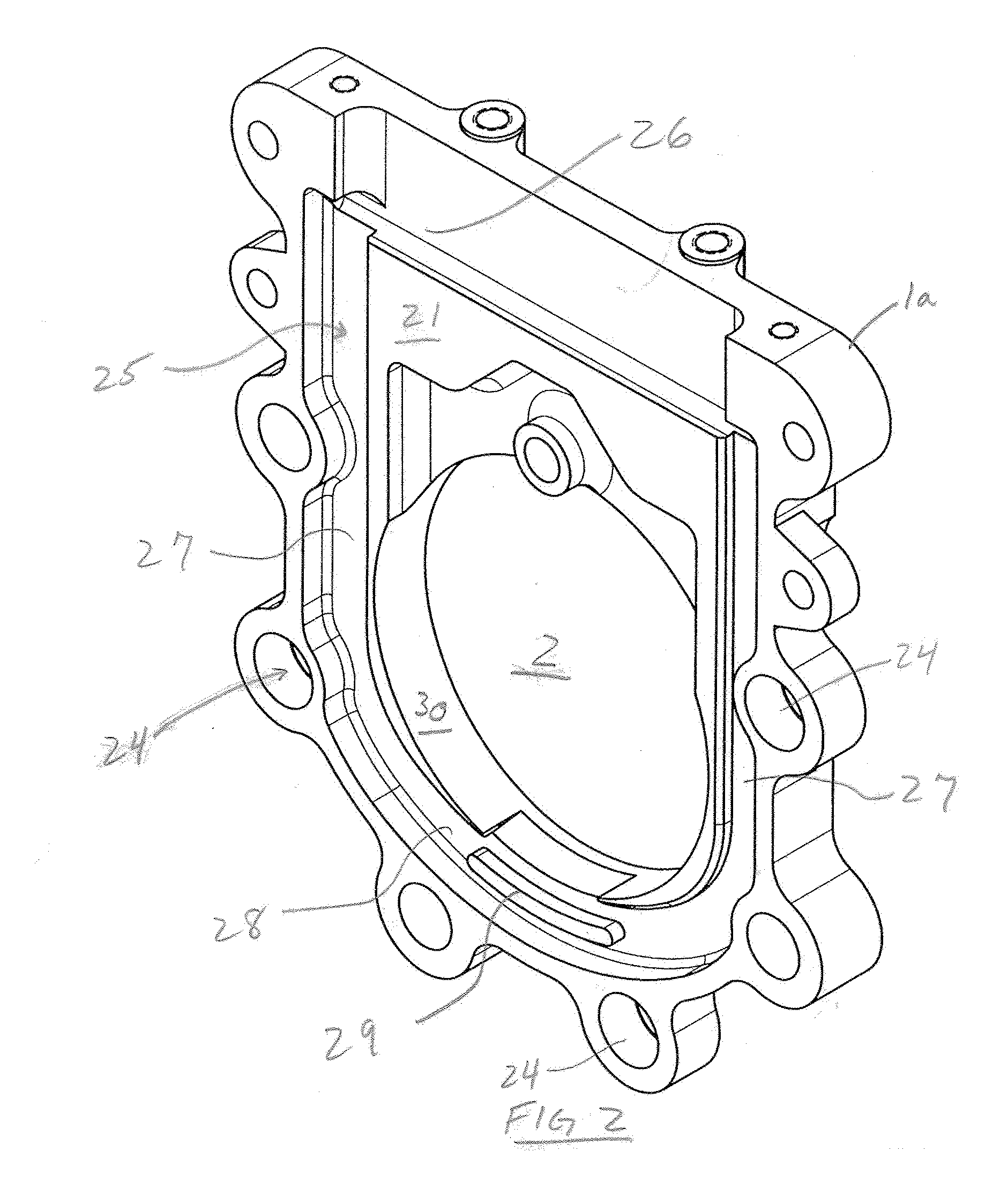
[0013]FIG. 1 is a perspective view of an embodiment of a knife gate valve for connection within a process line in accordance with the present invention. Valve 10 generally includes body halves 1a and 1b which define a valve housing 1 and a pathway or channel 2 through which process media flows. Body halves 1a and 1b form a gate channel which receives gate 6 which opens to allow process flow through valve 10 and closes to prevent process flow through valve 10. The body halves 1a and 1b are connected via a plurality of body bolts 4 received by threaded apertures 5 disposed in spaced relationship around body halves 1a and 1b. Yoke posts 18 are connected to body halves 1a and 1b at a first end and to yoke top plate 19 at a top or second end. Stem assembly 13 is connected to gate 6 via fastener block 8 which may include, for example fasteners 9a and 9b. Handwheel 22 is mounted above top plate 19 and when turned, rotates stemnut (not shown) to pull the stem linearly up and down which rais...


PUM


Abstract

A knife gate valve includes a reinforced valve seat which prevents displacement of the valve seat when the valve is opened and closed. The valve includes a valve body defined by a first and second body halves. The valve halves are assembled to define a flow path, a knife gate channel and a seat channel. A knife gate is disposed between the body halves and is adapted to traverse the gate channel. The knife gate is configured to be in an open position to allow process flow through the valve and a closed position to prevent process flow through the valve. A seat assembly is positioned within the channel guide and is defined by a horizontal segment, a pair of vertical segments and a lower segment. The seat assembly is compressed between the first and second valve body halves. At least one reinforcing plate is disposed within a portion of the horizontal segment, such that the horizontal segment maintains its rigidity when the knife gate traverses the seat assembly.

Description

BACKGROUND OF THE INVENTION[0001]The present invention relates generally to the field of flow control valves and the construction thereof. More specifically, the present invention relates to the internal components of valves including a reinforced elastomer seat that provides a sealing surface for the valve components.[0002]Flow control valves such as, for example, knife gate valves or line blind valves, are used to control the flow of process media and can be particularly well suited for use with abrasive and corrosive slurries used in, for example, the mining, pulp or paper industries. One form of gate valve known in the art includes a housing constructed of two halves that when coupled together form the valve housing and passageway therethrough. On opposite sides of the housing are connections for installing the valve in a pipe line, for example, the housing can be bolted to a flange end of a pipe. To control the flow of fluid through the valve, the valve includes a knife gate th...

Claims


Application Information

Patent Timeline
IPC IPC(8): F16K3/00
CPCF16K3/0227F16K27/044F16K3/0281F16K3/30
Inventor DEVINE, JR., DONALD L.MURAN, JOHN W.GAMBETTA, DAVID L.
Owner EMERSON VULCAN HLDG LLC
Why Eureka
Try Eureka