Non-uniform sampling to extend dynamic range of interferometric sensors

a sensor and dynamic range technology, applied in the field of optical signal processing techniques, can solve the problems that conventional demodulation techniques may require considerable computation resources and may even be impossible to implement in some signal processing systems

Active Publication Date: 2009-05-14
OPTOPLAN
View PDF10 Cites 49 Cited by
  • Summary
  • Abstract
  • Description
  • Claims
  • Application Information

AI Technical Summary

Problems solved by technology

Thus, conventional demodulation techniques may require considerable computation resources and may even be impossible to implement for some signal processing systems.
However, this technique requires a second high performance demodulator, an optical switch for routing signals between the two demodulators, and logic to control the optical switch.

Method used


Image

  • Non-uniform sampling to extend dynamic range of interferometric sensors
  • Non-uniform sampling to extend dynamic range of interferometric sensors
  • Non-uniform sampling to extend dynamic range of interferometric sensors

Examples


Embodiment Construction

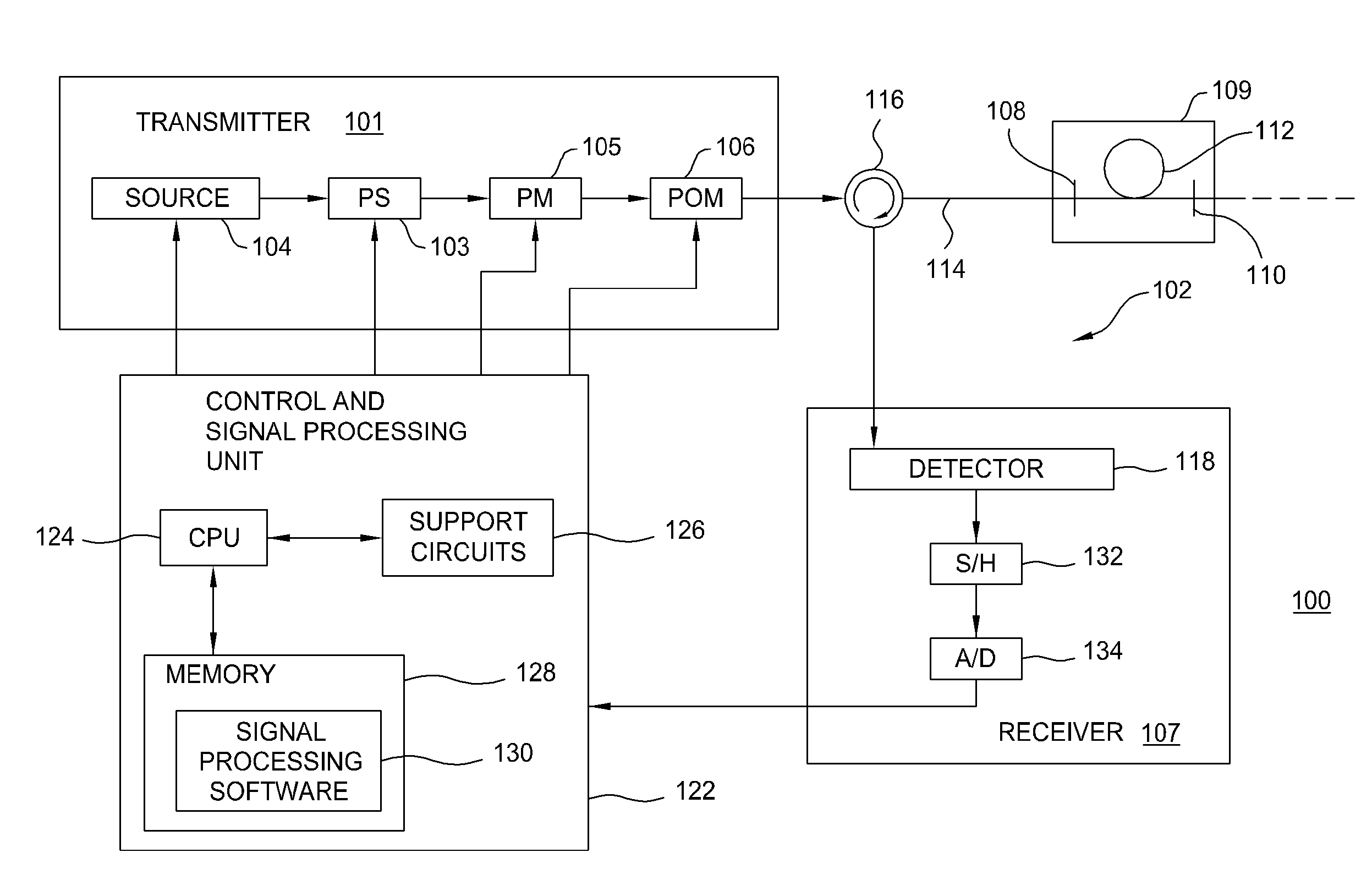
[0041]Embodiments of the invention generally relate to optical signal processing methods, apparatus, and systems that effectively reduce the bandwidth of the fringe signal in interferometric sensors.

[0042]Ocean bottom seismic (OBS) sensing systems are described below as a particular, but not limiting, example of an application in which embodiments of the present invention may be used to advantage. However, those skilled in the art will recognize that the concepts described herein may be used to similar advantage in a wide variety of other applications in which a large number of optical sensors are interrogated.

[0043]Further, while embodiments of the present invention will be described with reference to optical fibers, those skilled in the art will recognize that any type of suitable optical waveguide may be used as well. Further, while embodiments of the present invention will be described with reference to sensor elements utilizing inline reflective elements such as fiber Bragg gra...


PUM


Abstract

Methods and apparatus for interrogating optical sensors with high slew rates using non-uniform sampling are provided. The transmission of optical signals in a non-uniform pattern is employed to allow for demodulation of fringe rates exceeding the commonly understood Nyquist frequency limit given as one half of the mean sampling frequency. By monitoring the time dependent fringe frequency and assuming that the fringe frequency has a limited bandwidth, only a limited bandwidth smaller than the Nyquist bandwidth around the instantaneous fringe frequency needs to be reconstructed at any time.

Description

BACKGROUND OF THE INVENTION[0001]1. Field of the Invention[0002]Embodiments of the present invention generally relate to optical signal processing techniques and, more particularly, to optical signal processing of interrogation signals received from time-division multiplexed (TDM) interferometers.[0003]2. Description of the Related Art[0004]Marine seismic exploration surveys for the exploration and monitoring of hydrocarbon producing zones and reservoirs utilize seismic cables having sensor arrays, i.e., a plurality of sensor stations interconnected by sections of cable. The cable arrays may include a large number of sensor stations (e.g., several hundreds or thousands) and may be buried in a predetermined pattern on the ocean floor. Optical sensors may be particularly well-suited for ocean bottom seismic (OBS) applications, due to their robust nature, lack of sensitive electronics, and potential for lightweight sensors and cable assemblies that are relatively inexpensive to install...

Claims


Application Information

Patent Timeline
Patent Type & Authority Applications(United States)
IPC IPC(8): G01B9/02
CPCG01H9/004G01V1/226G01V1/24G01D5/35396G01P15/093G01D5/35312G01V2210/1427
Inventor RONNEKLEIV, ERLENDWAAGAARD, OLE HENRIK
Owner OPTOPLAN
Why Eureka
Try Eureka