Light-emitting intra-cavity interferometric sensors

a technology of interferometry and light-emitting sensors, applied in the field of optical sensors, can solve the problems of “imbalanced” geometry, mismatching of lengths of branch segments by 2.4%, and serious drawbacks of wet immunoassays, and achieves the effects of high sensitivity, minimal non-specific binding effects, and high sensitivity of interferometric integrated optic devices

Inactive Publication Date: 2010-09-16
TEL AVIV UNIV FUTURE TECH DEVMENT
View PDF23 Cites 12 Cited by
  • Summary
  • Abstract
  • Description
  • Claims
  • Application Information

AI Technical Summary

Benefits of technology

[0012]In some embodiments, at least one of the waveguide branches is functionalized (bio-bound or chemo-bound) with probes or “receptors” (e.g. antibodies), while another branch serves as reference. In such embodiments, upon binding of target molecules to the receptors, the propagation coefficient of the guided light (effective index of the WG) is altered at a different rate in the functionalized branch. This leads to a spectral shift of the positive interference pattern of the resonator, which in turn is transformed into a shift of the emitted spectrum of the entire device. Such a structure provides a biological (or chemical) reference which is inherent and integral to the device and which minimizes nonspecific binding effects. In addition, in such a structure, the binding events in the functionalized branch are transformed by interference into a maximal spectral shift, which maximizes the sensitivity. Thus, a mechanism is created to achieve the high sensitivity of interferometric integrated optics devices while the sensing is encoded in the internally generated and out-coupled emitted light spectrum.

Problems solved by technology

The device of Sanford et al. has an “imbalanced” geometry in which the branch segments are mismatched in length by 2.4%.
Nevertheless, wet immunoassays have some serious drawbacks.
For example, changes in temperature of the flowing sample liquid strongly impact its refraction index and disrupt the optical reading.
The reading is also disturbed by turbulence in the flow.
These issues are solved by a sophisticated flow system with a delicate and tight control of the flowing sample liquid temperature.
This complexity significantly raises the cost of wet optical immunoassay systems, rendering them inappropriate for point-of-care applications.

Method used


Image

  • Light-emitting intra-cavity interferometric sensors
  • Light-emitting intra-cavity interferometric sensors
  • Light-emitting intra-cavity interferometric sensors

Examples


example

[0042]C Reactive Protein (CRP) (152315, MP) was chosen as a model for an analyte. CMR is a pentameric plasma protein, which its blood levels indicate risk of cardio vascular seizures. Hence, there is a need for a simple, cheap and rid way to measure its concentration in blood. BSA (Bovine serum albumin, A7906, Sigma) served as a control protein.

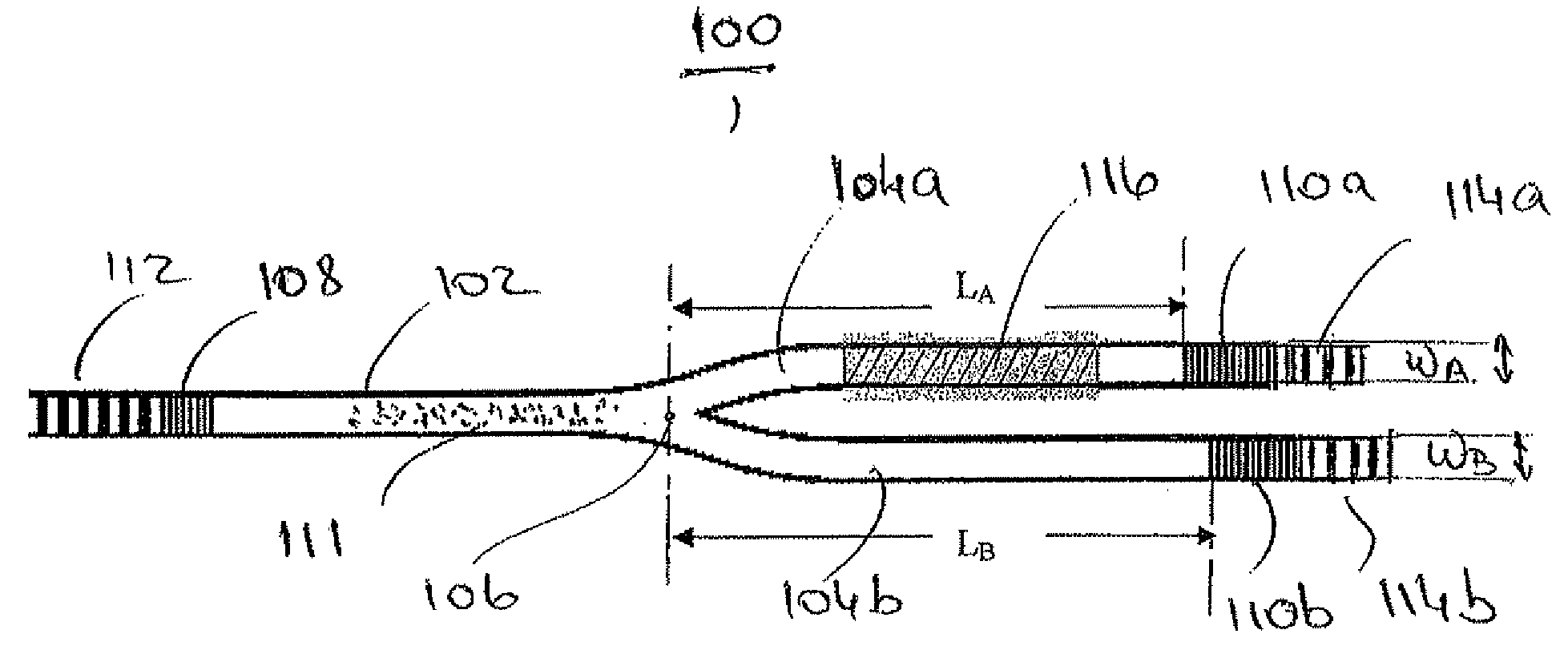
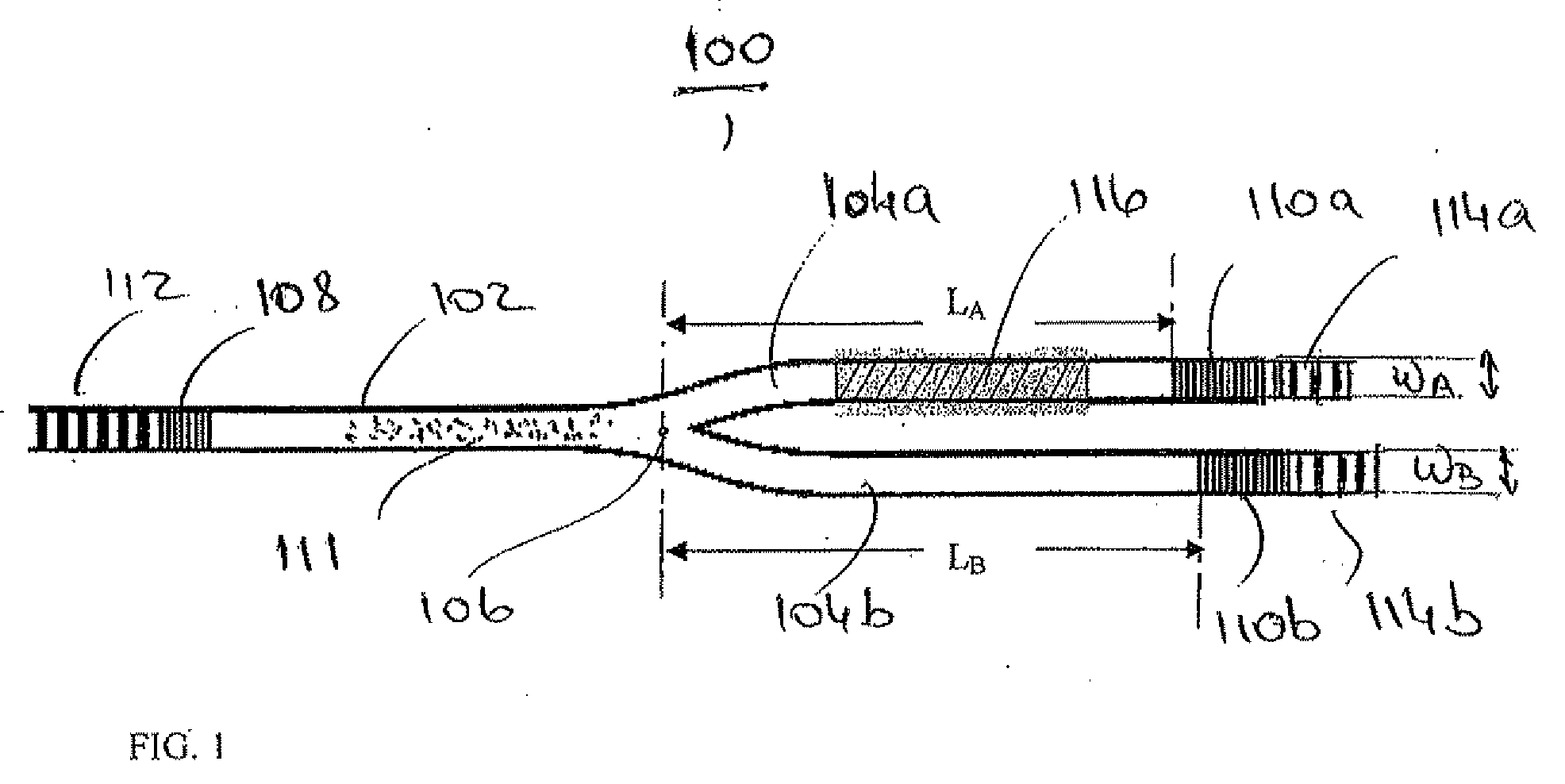
[0043]Sol-gel ICI laser sensors with three exemplary sets of imbalanced branch lengths LA and LB were designed and fabricated in a sol-gel layer on top of a silica-on-silicon substrate. Details of the sol-gel waveguide fabrication may be found in Asher Peled et al., “Amplification from Nd+3 doped Si—Ti sol-gel channel waveguides”, J. Optical Materials, 2009, in press, and in Peled 2009. Each design was fabricated in a number of copies. Sensor type #1, where LA and LB were respectively 3 mm and 3.06 mm; Sensor type #2, where LA and LB were respectively 10 mm and 10.06 mm; and Sensor type #3, where LA and LB were respectively 20 mm and 20.06 mm...


PUM


Abstract

Light-emitting intra-cavity interferometric (ICI) optical sensors based on channel waveguide structures which include an internal light emitting material and a functionalized region. In some embodiments, the waveguides are made of a sol-gel which incorporates the light emitting material. In some embodiments, the waveguide structure includes an ICI resonator backbone and the ICI sensor is a laser sensor. In some embodiments, the resonator backbone has an interferometric Y-branch shape. In some embodiments, the resonator backbone has a Mach Zehnder interferometer shape. In some embodiments, an ICI laser sensor has an interferometric arrayed waveguide grating shape. In some embodiments, an ICI sensor may be remotely optically pumped and remotely read.

Description

FIELD OF THE INVENTION[0001]The invention is related to the general field of optical sensors, and more particularly to light emitting intra-cavity interferometric (ICI) channel waveguide (WG) sensors.BACKGROUND OF THE INVENTION[0002]Optical sensing devices which use various sensing principles are known. A good background description on the state of the art is provided in U.S. Pat. No. 7,447,391 to Asher Peled et al., as well as in “Novel monolithic amplifiers, lasers and intra-cavity interferometric sensors based on Nd-doped sol-gel”, PhD thesis, Asher Peled, Tel Aviv University, submitted November 2008, to be published 2009 (hereinafter “Peled 2009”), both of which are incorporated herein by reference in their entirety. In particular, interferometric optical sensors in various configurations, such as Mach Zehnder interferometers (MZI) and Young interferometers are known to have the best reported sensitivities.[0003]U.S. Pat. No. 7,447,391 discloses biological and chemical optical s...

Claims


Application Information

Patent Timeline
Patent Type & Authority Applications(United States)
IPC IPC(8): G01B9/02G02B6/00
CPCG01N2021/7779G01N21/7703
Inventor PELED, ASHERNATHAN, MENACHEMRUSCHIN, SHLOMOBETZALEL, YIFAATRISHPON, JUDITH
Owner TEL AVIV UNIV FUTURE TECH DEVMENT
Why Eureka
Try Eureka