Implantable electrode positioning

a technology of implantable electrodes and positioning electrodes, which is applied in the direction of external electrodes, sensors, artificial respiration, etc., can solve the problems of difficult temporary waking of patients from generals, unreliable reports provided by drowsy patients, and limited feedback regarding the location of paraesthesia

Active Publication Date: 2020-03-17
SALUDA MEDICAL PTY LTD
View PDF335 Cites 28 Cited by
  • Summary
  • Abstract
  • Description
  • Claims
  • Application Information

AI Technical Summary

Benefits of technology

[0030]In some embodiments of the invention, the probe electrode is surgically introduced via the same incision as the electrode array. In some such embodiments the probe electrode may be fed from the incision in a first caudorostral direction which is opposite to a second caudorostral direction in which the electrode array is introduced. In further such embodiments, in which the nerve is the dorsal column, the probe electrode may be temporarily fixed so as to be positioned in the same or a nearby vertebral segment as the electrode array. Temporarily fixing the probe electrode near the electrode array, such as in the same vertebral segment or in an adjacent vertebral segment, or nearby within a small number of vertebral segments, is desirable because while the fibres of the dorsal column run approximately parallel over the distances of a few vertebral segments, any twist or rotation of or within the spinal cord could produce a misalignment of the electrophysiological midline relative to the anatomical midline and this risk rises beyond a few vertebral segments, and this might alter or make unclear the spatial representation of the physiological midline of the nerve which is provided by the ECAPs when first evoked. Temporarily fixing the probe electrode near the electrode array is also advantageous when it permits a single surgical incision to be used, such as a single laminectomy, to implant both the probe electrode and the electrode array.
[0033]The probe electrode may comprise multiple elements which are caudorostrally spaced apart along the nerve, for example to facilitate embodiments in which the probe electrode senses ECAPs evoked by the electrode array, and / or to enable an optimally caudorostrally positioned probe electrode element to be selected in order to maximise recruitment and or measurement sensitivity.
[0036]The present invention thus recognises that sensing compound action potentials by use of electrodes of an electrode array, can be used to monitor the placement of the electrode array during surgery. The present invention thus provides a method to better assess the position of the electrode array, in the dorsoventral, caudorostral and / or mediolateral direction, quickly and simply while the patient is under general anaesthesia, without requiring scalp electrodes for somatosensory cortex monitoring, for example.
[0038]The stimuli may be delivered by the probe electrode, and evoked ECAPs may be sensed by the electrode array. Alternatively, the stimuli may be delivered by the electrode array, and evoked ECAPs may be sensed by the probe electrode, and it is to be understood that in all embodiments described herein the positioning roles of the probe electrode and the electrode array may be reversed, within the scope of the present invention. Moreover, over time the source of stimuli may alternate between the probe electrode and the electrode array, which may assist with position resolution.

Problems solved by technology

Temporarily waking a patient from a general can be difficult, and even once the patient is awake the reports provided by a drowsy patient are often unreliable.
Because the patient is not fully alert when temporarily awoken from general anaesthesia, and is otherwise asleep during the remainder of the implantation procedure, they can only provide limited feedback regarding the location of the paraesthesia, or regarding any complications arising from lead placement.
Although complications are rare they can be very serious.
However, fluoroscopic imaging resolution is relatively imprecise, compared to the accuracy requirements of lead placement.
Moreover, complications of implanting a surgical lead while a patient is asleep can include damage to the spinal cord due to direct pressure of the lead as it is placed into the epidural space, or post-operative damage due to the development of a hematoma over the lead, which can then create pressure on the lead and damage the dorsal column axons.
Consequently, implanting a patient under a general anaesthetic by reference to anatomical markers can result in the paddle electrode array not providing equal stimulation and paraesthesia to both sides of the body.
This collision results in an observed depression of the somatosensory responses.
However, this has been less successful as when considering a sensory homunculus the representation of the legs for example on the sensory cortex is small, and buried within the longitudinal fissure of the brain.
Since many chronic pain patients have lower extremity pain this method has not proved to be useful.
The dorsoventral position of the electrode array is also of importance, as a large nerve-to-electrode distance can increase the stimulus power required to evoke neural responses and thus decrease battery life.
On the other hand, bringing the electrode array too close to the nerve can apply pressure or direct trauma to the nerve and cause temporary or even permanent nerve damage.
However, the dorsoventral position is also difficult to accurately determine during surgery.
Occasionally a surgeon may take a lateral view image with fluoroscope, however these images are not of sufficient resolution to sufficiently accurately judge the proximity of the array to the cord.

Method used


Image

  • Implantable electrode positioning
  • Implantable electrode positioning
  • Implantable electrode positioning

Examples


Embodiment Construction

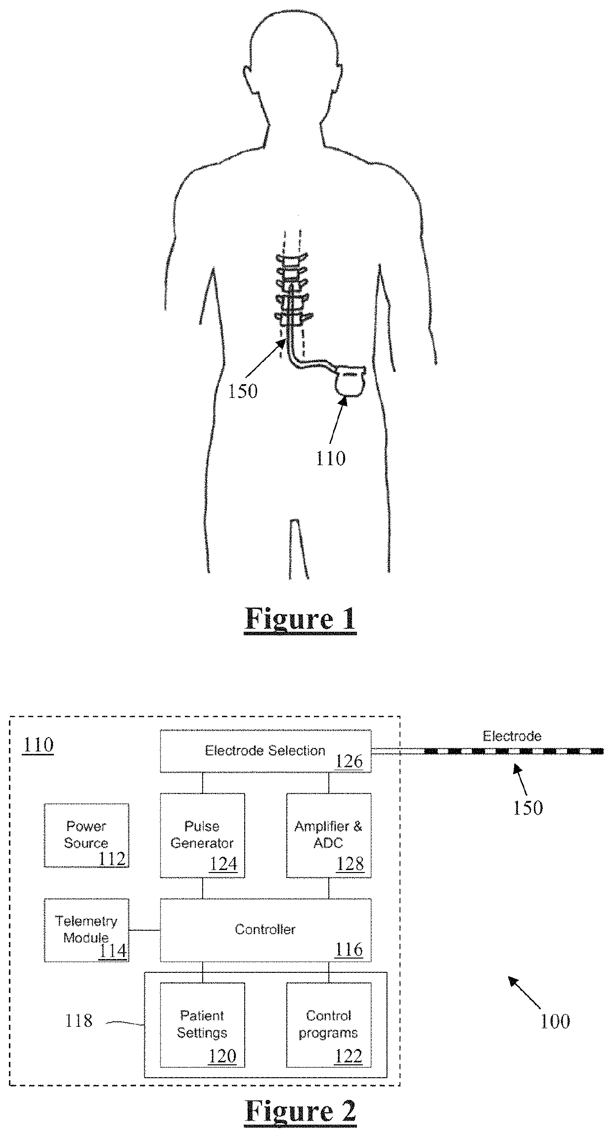
[0054]FIG. 1 schematically illustrates an implanted spinal cord stimulator 100. Stimulator 100 comprises an electronics module 110 implanted at a suitable location in the patient's abdomen and an electrode assembly 150 implanted within the epidural space and connected to the module 110 by a suitable lead.

[0055]FIG. 2 is a block diagram of the implanted neurostimulator 100. Module 110 contains a battery 112 and a telemetry module 114. In embodiments of the present invention, any suitable type of transcutaneous communication, such as infrared (IR), electromagnetic, capacitive and inductive transfer, may be used by telemetry module 114 to transfer power and / or data between an external device and the electronics module 110.

[0056]Module controller 116 has an associated memory 118 storing patient settings 120, control programs 122 and the like. Controller 116 controls a pulse generator 124 to generate stimuli in the form of current pulses in accordance with the patient settings 120 and co...


PUM


Abstract

A method of surgically positioning an electrode array at a desired implantation location relative to a nerve. A temporary probe electrode is temporarily positioned adjacent to the nerve and at a location which is caudorostrally separate to the desired implantation location of the electrode array. The implanted position of the probe electrode is temporarily fixed relative to the nerve. During implantation of the electrode array, electrical stimuli are applied from one of the temporarily fixed probe electrode and the electrode array, to evoke compound action potentials on the nerve. Compound action potentials evoked by the stimuli are sensed from at least one electrode of the other of the temporarily fixed probe electrode and the electrode array. From the sensed compound action potentials a position of the electrode array relative to the nerve is determined.

Description

CROSS-REFERENCE TO RELATED APPLICATIONS[0001]This application is a national stage of Application No. PCT / AU2015 / 050753, filed Nov. 30, 2015, which application claims the benefit of Australian Provisional Patent Application No. 2014905030 filed Dec. 11, 2014, the disclosures of which are incorporated herein by reference in their entireties.TECHNICAL FIELD[0002]The present invention relates to monitoring compound action potentials during surgery to assist with implantable electrode placement.BACKGROUND OF THE INVENTION[0003]A range of implanted neural devices exist, including: spinal cord implants which electrically stimulate the spinal column in order to suppress chronic pain; cochlear implants which electrically stimulate the auditory nerve to produce a hearing sensation; deep brain stimulators which electrically stimulate selected regions of the brain to treat conditions such as Parkinson's disease or epilepsy; and neural bypass devices which electrically stimulate either afferent ...

Claims


Application Information

Patent Timeline
Patent Type & Authority Patents(United States)
IPC IPC(8): A61B34/20A61N1/372A61N1/36A61B5/00A61B5/04A61N1/05
CPCA61B5/686A61B5/4893A61B5/407A61N1/372A61N1/36185A61B5/04001A61B34/20A61N1/0553A61N1/36135A61N1/36071A61B2034/2053A61B2505/05A61B2562/046A61N1/3614A61B5/24A61B5/1118A61B5/388A61B5/4029
Inventor PARKER, JOHN LOUISOBRADOVIC, MILAN
Owner SALUDA MEDICAL PTY LTD
Why Eureka
Try Eureka