Adaptive mixing for high slew rates

a high-slew rate, adaptive mixing technology, applied in the direction of converting sensor output, measuring devices, instruments, etc., can solve the problems that conventional demodulation techniques may require considerable computation resources and may even be impossible to implement in some signal processing systems

Active Publication Date: 2009-04-30
OPTOPLAN
View PDF11 Cites 11 Cited by
  • Summary
  • Abstract
  • Description
  • Claims
  • Application Information

AI Technical Summary

Benefits of technology

[0013]Yet another embodiment of the present invention is a method for detecting a sensor phase in an interferometric system. The method generally includes estimating a parameter dependent on the phase of a detected interference signal, obtaining a local oscillator phasor based on the parameter dependent on the phase of the detected interference signal, mixing the detected interference signal with the local oscillator phasor in one or more steps to create a mixed signal phasor, signal processing the mixed signal phasor and the parameter dependent on the phase of the detected interference signal, and extracting the sensor phase from the processed mixed signal phasor and the processed parameter. The parameter dependent on the phase of the detected interference signal may be the phase or the frequency of the detected interference signal.
[0014]Yet another embodiment of the present invention provides an interferometric system. The interferometric system generally includes a plurality of optical sensors; a transmitter configured to transmit optical signals to the plurality of optical sensors; a receiver configured to detect interference signals produced by the plurality of optical sensors and based on the transmitted optical signals; and a signal processing unit. The signal processing unit is generally configured, for each of the detected interference signals, to mix the detected interference signal with a local oscillator phasor in one or more steps to create a mixed signal, obtain a parameter dependent on the phase of the mixed signal, obtain the local oscillator phasor based on the parameter, signal process the mixed signal and the parameter, and extract the sensor phase from the processed mixed signal and the processed parameter.
[0015]Yet another embodiment of the present invention provides an interferometric system. The interferometric system generally includes a plurality of optical sensors; a transmitter configured to transmit optical signals to the plurality of optical sensors; a receiver configured to detect interference signals produced by the plurality of optical sensors and based on the transmitted optical signals; and a signal processing unit. The signal processing unit is generally configured, for each of the detected interference signals, to estimate a parameter dependent on the phase of the detected interference signal, obtain a local oscillator phasor based on the parameter, mix the detected interference signal with the local oscillator phasor in one or more steps to create a mixed signal phasor, signal process the mixed signal phasor and the parameter, and combine the processed mixed signal phasor with the processed parameter to extract the sensor phase.

Problems solved by technology

Thus, conventional demodulation techniques may require considerable computation resources and may even be impossible to implement for some signal processing systems.
However, this technique requires a second high performance demodulator, an optical switch for routing signals between the two demodulators, and logic to control the optical switch.

Method used


Image

  • Adaptive mixing for high slew rates
  • Adaptive mixing for high slew rates
  • Adaptive mixing for high slew rates

Examples


Embodiment Construction

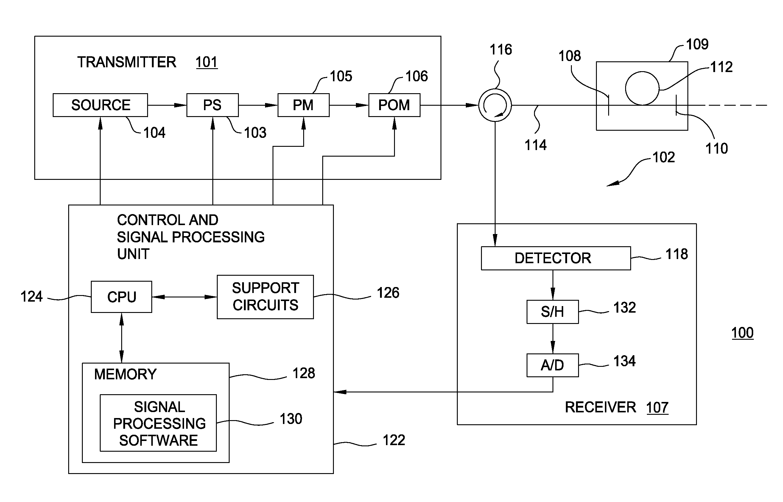
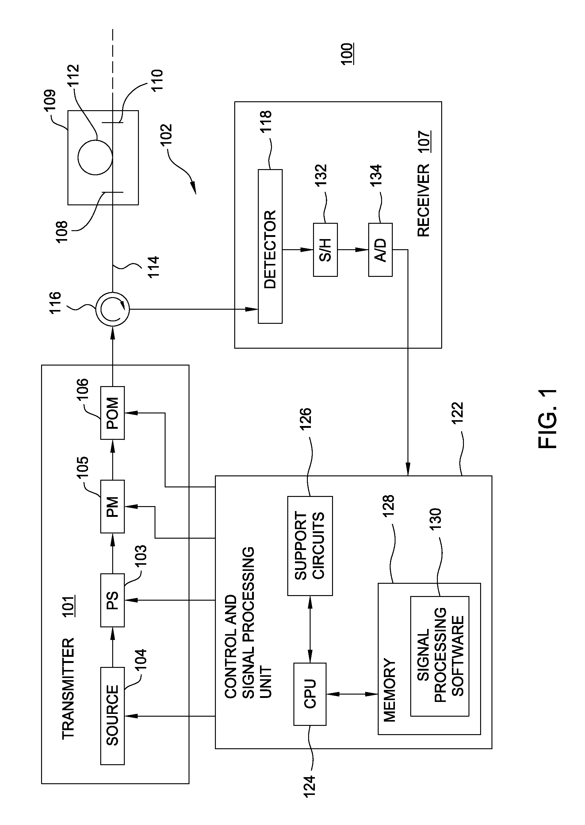
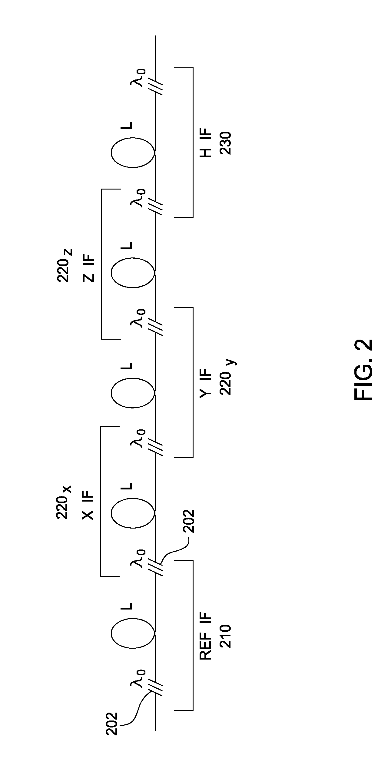
[0027]Embodiments of the invention generally relate to optical signal processing methods, apparatus, and systems that effectively reduce the bandwidth of the fringe signal in interferometric sensors.

[0028]Ocean bottom seismic (OBS) sensing systems are described below as a particular, but not limiting, example of an application in which embodiments of the present invention may be used to advantage. However, those skilled in the art will recognize that the concepts described herein may be used to similar advantage in a wide variety of other applications in which a large number of optical sensors are interrogated.

[0029]Further, while embodiments of the present invention will be described with reference to optical fibers, those skilled in the art will recognize that any type of suitable optical waveguide may be used as well. Further, while embodiments of the present invention will be described with reference to sensor elements utilizing inline reflective elements such as fiber Bragg gra...


PUM


Abstract

A method and apparatus for demodulation of detected fringes from interferometric sensors with high slew rates are provided. A detected interference signal may be mixed with a local oscillator phasor to obtain a mixed signal, the local oscillator being controlled to produce a frequency that roughly matches the fringe frequency of the interference signal. A sensor phase estimate may be obtained from the detected interference signal or the mixed signal. The local oscillator signal can be computed from the sensor phase estimate. The mixed signal and the sensor phase estimate may be low pass filtered and decimated and the resulting decimated mixed signal and decimated sensor phase estimate may be processed and combined with moderate processing power requirements in an effort to accurately measure the sensor phase for the interferometric sensor.

Description

BACKGROUND OF THE INVENTION[0001]1. Field of the Invention[0002]Embodiments of the present invention generally relate to optical signal processing techniques and, more particularly, to optical signal processing of interrogation signals received from time-division multiplexed (TDM) interferometers.[0003]2. Description of the Related Art[0004]Marine seismic exploration surveys for the exploration and monitoring of hydrocarbon producing zones and reservoirs utilize seismic cables having sensor arrays, i.e., a plurality of sensor stations interconnected by sections of cable. The cable arrays may include a large number of sensor stations (e.g., several hundreds or thousands) and may be buried in a predetermined pattern on the ocean floor. Optical sensors may be particularly well-suited for ocean bottom seismic (OBS) applications, due to their robust nature, lack of sensitive electronics, and potential for lightweight sensors and cable assemblies that are relatively inexpensive to install...

Claims


Application Information

Patent Timeline
Patent Type & Authority Applications(United States)
IPC IPC(8): H04B1/10
CPCG01H9/004G01D5/35303G01D5/35358
Inventor WAAGAARD, OLE HENRIKRONNEKLEIV, ERLEND
Owner OPTOPLAN
Why Eureka
Try Eureka