Water-assisted air cooling for a row of cabinets

a technology of rowing cabinets and water-assisted air cooling, which is applied in the direction of electrical equipment, electrical apparatus, electrical apparatus contruction details, etc., can solve the problems of affecting the operation of the equipmen

Inactive Publication Date: 2009-05-14
IBM CORP
View PDF12 Cites 33 Cited by
  • Summary
  • Abstract
  • Description
  • Claims
  • Application Information

AI Technical Summary

Benefits of technology

[0021]In another aspect, a method for cooling includes: (a) positioning a plurality of heat-producing devices in a plurality of cabinets arranged in a row; (b) positioning a plurality of heat exchangers in a space between the cabinets and adjacent to the cabinets, thereby alternating the cabinets and the heat exchangers in the row; (c) directing flow of a first fluid through the heat-producing devices, cabinets, and heat exchangers for cooling the first fluid; and (d) positioning a plurality of fluid-moving devices adjacent the heat-producing devices for encouraging flow of the first fluid through the cabinets' heat-producing devices and through the heat exchangers, thereby encouraging heat transfer from the first fluid to a second fluid in each of the heat exchangers.

Problems solved by technology

For cabinets that dissipate large quantities of heat, this requirement is often burdensome on the infrastructure of the room 140 because it requires significant investment in air-conditioning units 152, a large under-floor space 150, and a disruption of airflow patterns to other, already-existing equipment in the room.
This requirement inevitably incurs pressure loss, leading to reduced flow rate V and increased temperature of the electronics 134.
Unobstructed holes are difficult to insure for all installations, because raised-floors are not standard worldwide, for example, the pitch p of the removable tiles 146 may differ from country to country.

Method used


Image

  • Water-assisted air cooling for a row of cabinets
  • Water-assisted air cooling for a row of cabinets
  • Water-assisted air cooling for a row of cabinets

Examples


Embodiment Construction

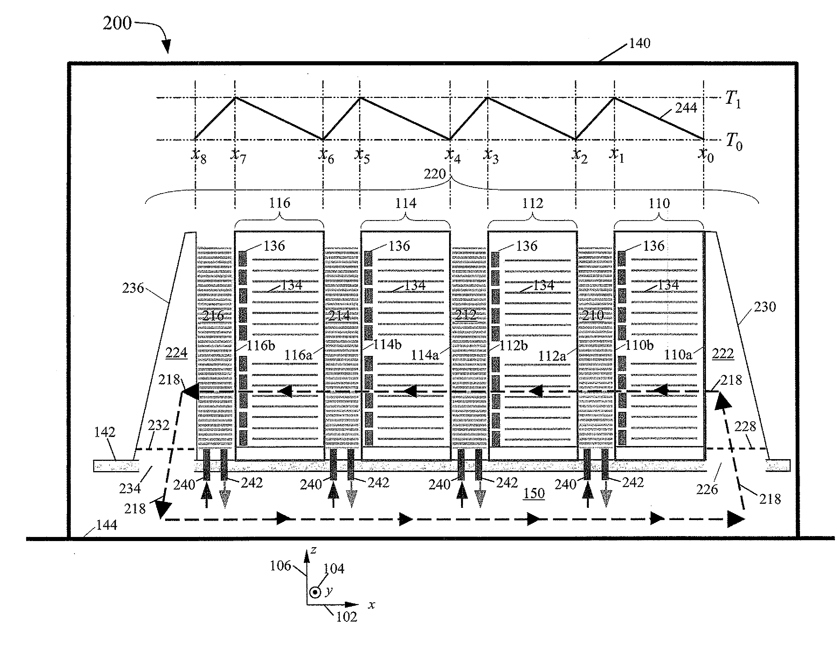
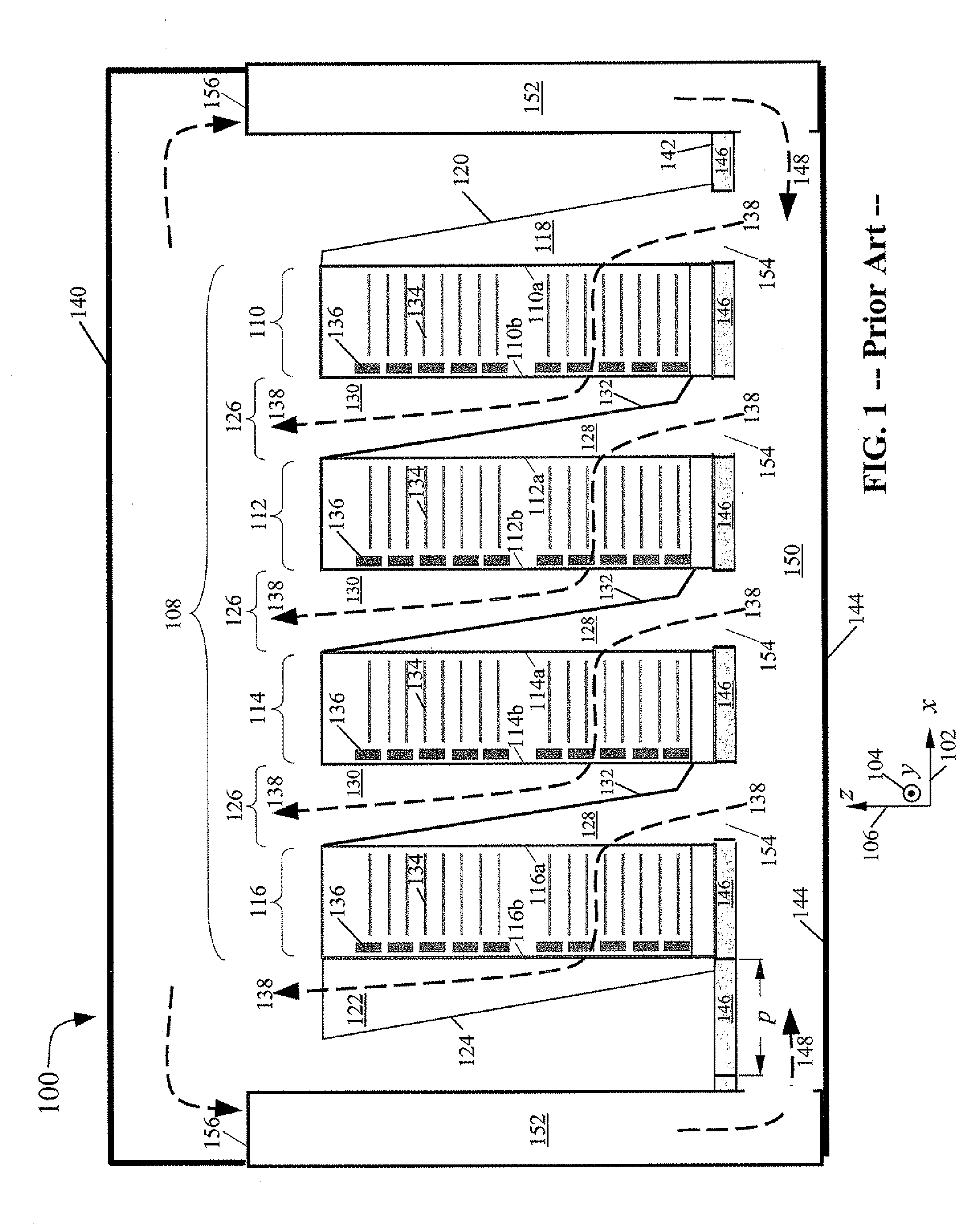
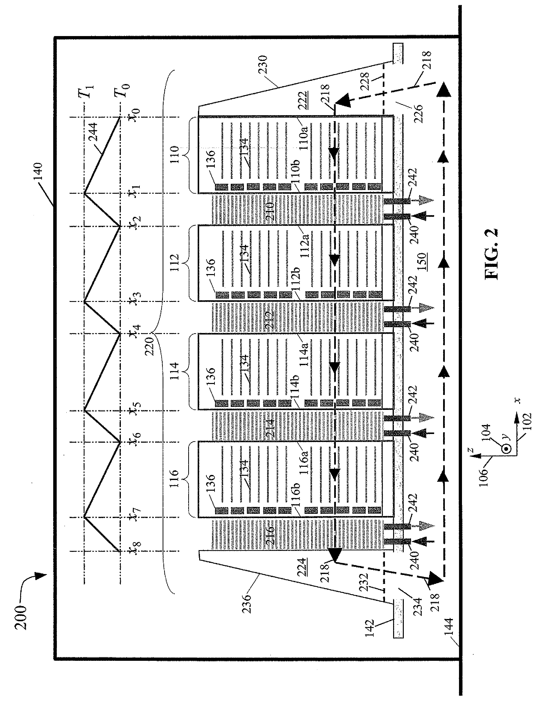
[0032]Referring to FIG. 2, an illustrative embodiment of a cooling apparatus 200 according to the present invention uses the same reference numerals for like elements as the prior art apparatus 100 shown in FIG. 1. However, the apparatus 200 differs from the prior art apparatus 100 in at least two significant ways. First, on the downstream faces of each cabinet 110, 112, 114, 116, the present invention employs, in contrast to the prior art air plenums 126, 122, a series of air-to-water heat exchangers 210, 212, 214, 216. Second, the present invention uses, in place of the prior art's multiple S-shaped air paths 138, a single, row-wise airflow path 218 that travels substantially in the −x direction, straight through an entire flow-through row 220. The flow-through row 220 comprises the cabinets 110, 112, 114, 116; the heat exchangers 210, 212, 214, 216, and optionally an intake plenum and an exhaust plenum such as a bottom-intake plenum 222, and a bottom-exhaust plenum 224, respectiv...


PUM


Abstract

A cooling apparatus and method including a plurality of heat-producing devices positioned in a plurality of cabinets arranged in a row that allows flow of a first fluid through the heat-producing devices and cabinets where the flow is directed from an upstream end of the row to a downstream end of the row. The cabinets have a space therebetween wherein a heat exchanger is positioned between and adjacent to the cabinets, thereby the cabinets and heat exchangers alternate in the row. Each heat exchanger allows flow of a second fluid therethrough for cooling the first fluid. A fluid-moving device is positioned adjacent the heat-producing devices for encouraging flow of the first fluid through the cabinets' heat-producing devices and through the heat exchangers, thereby encouraging heat transfer in each of the heat exchangers from the first fluid to the second fluid.

Description

FIELD OF THE INVENTION[0001]The present invention is related to devices and methods for cooling heat-producing equipment, and more specifically, is related to devices for cooling heat-producing electronic equipment arranged in a row of cabinets.BACKGROUND OF THE INVENTION[0002]Referring to FIG. 1 and the Cartesian coordinate system which comprises an x axis 102, a y axis 104, and a z axis 106 that are mutually orthogonal, a known air-cooling apparatus 100, described in U.S. Pat. No. 7,085,133, which is incorporated by reference herein in its entirety, includes a row of cabinets 108, including cabinets 110, 112, 114, 116 arrayed along the x axis 102. The row of cabinets 108 includes a first cabinet 110 located at the +x end of the row and a last cabinet 116 located at the −x end of the row. An arbitrary number of additional interior cabinets, such as cabinets 112 and 114 shown in FIG. 1, are positioned between the first cabinet 110 and the last cabinet 116.[0003]An intake end-plenum ...

Claims


Application Information

Patent Timeline
Patent Type & Authority Applications(United States)
IPC IPC(8): H05K7/20
CPCH05K7/2079
Inventor HALL, SHAWN A.
Owner IBM CORP
Why Eureka
Try Eureka