Adaptive variable geometry turbocharger strategy

a turbocharger and variable geometry technology, applied in the direction of liquid fuel engines, electric control, instruments, etc., can solve the problems of inability to accurately memorize the minimum-flow actuator actuation position, wear and tear of components in the actuation system of the variable nozzle mechanism, and inability to adjust the minimum-flow actuator

Active Publication Date: 2009-05-14
GARRETT TRANSPORATION I INC
View PDF11 Cites 42 Cited by
  • Summary
  • Abstract
  • Description
  • Claims
  • Application Information

AI Technical Summary

Benefits of technology

[0010]Advantageously, sensor readings during the hard-stop actuation provide information on the wear of the components of the actuation system, and thus provide a measure on the accuracy with which the actuation system is directing the variable geometry members to their respective reference position(s). Further, the same sensor readings may provide information to reestablish the reference-position information so as to account for the wear of the components and thereby better provide for the vanes to be actuated to their reference positions.

Problems solved by technology

As the turbocharger ages, component wear occurs in the actuation system of the variable nozzle mechanism.
As this wear builds up in actuation system components such as rods and gears that mechanically link the actuator to the VNT vanes, the wear creates a slowly increasing offset between the intended vane position and the actual vane position achieved under aerodynamic loading.
Due to this drift (i.e., the slowly increasing offset), the memorized minimum-flow actuator actuation position is no longer accurate, and the mass flow no longer reaches the desired mass flow value when the actuator is directed to actuate the vanes to their minimum-flow position.
As a result, the turbocharger and related engine operate less efficiently, and emissions increase.
These changes can manifest as a noticeable reduction in vehicle performance and changes in transient behavior.

Method used


Image

  • Adaptive variable geometry turbocharger strategy
  • Adaptive variable geometry turbocharger strategy
  • Adaptive variable geometry turbocharger strategy

Examples


Embodiment Construction

[0016]The invention summarized above and defined by the enumerated claims may be better understood by referring to the following detailed description, which should be read with the accompanying drawings. This detailed description of particular preferred embodiments of the invention, set out below to enable one to build and use particular implementations of the invention, is not intended to limit the enumerated claims, but rather, it is intended to provide particular examples of them.

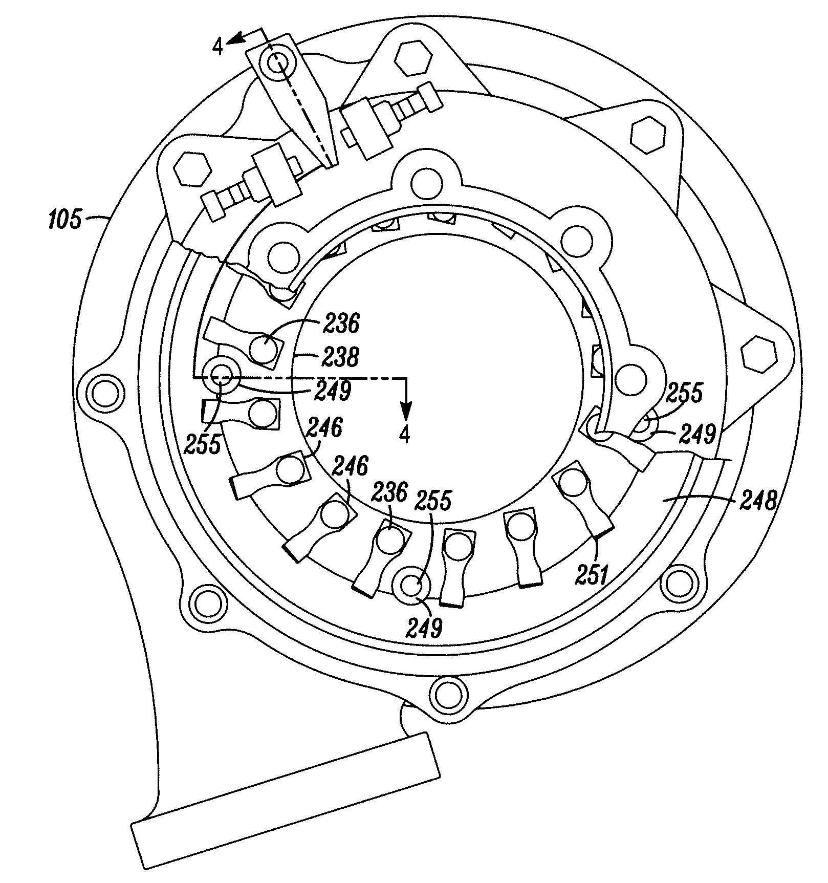
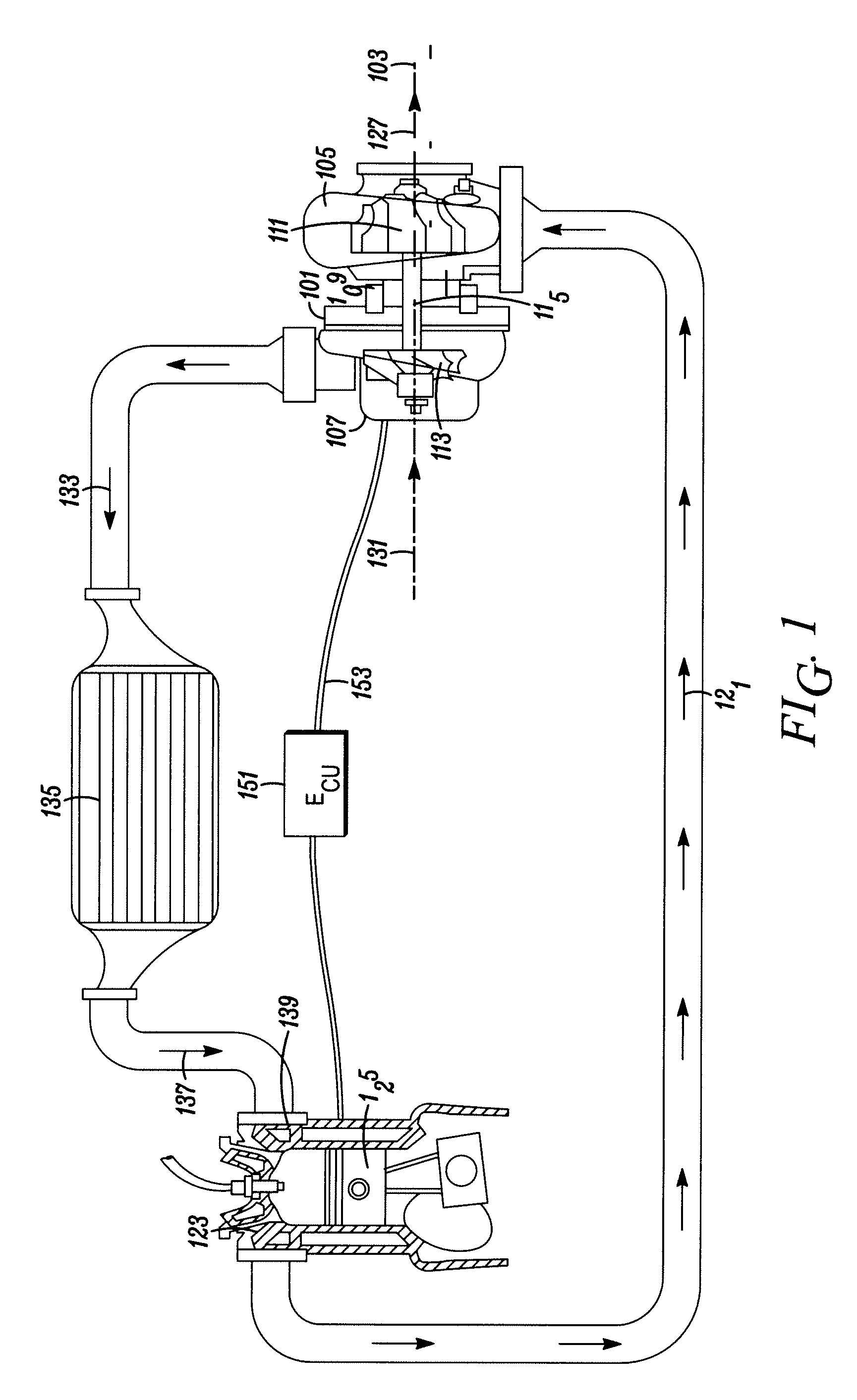
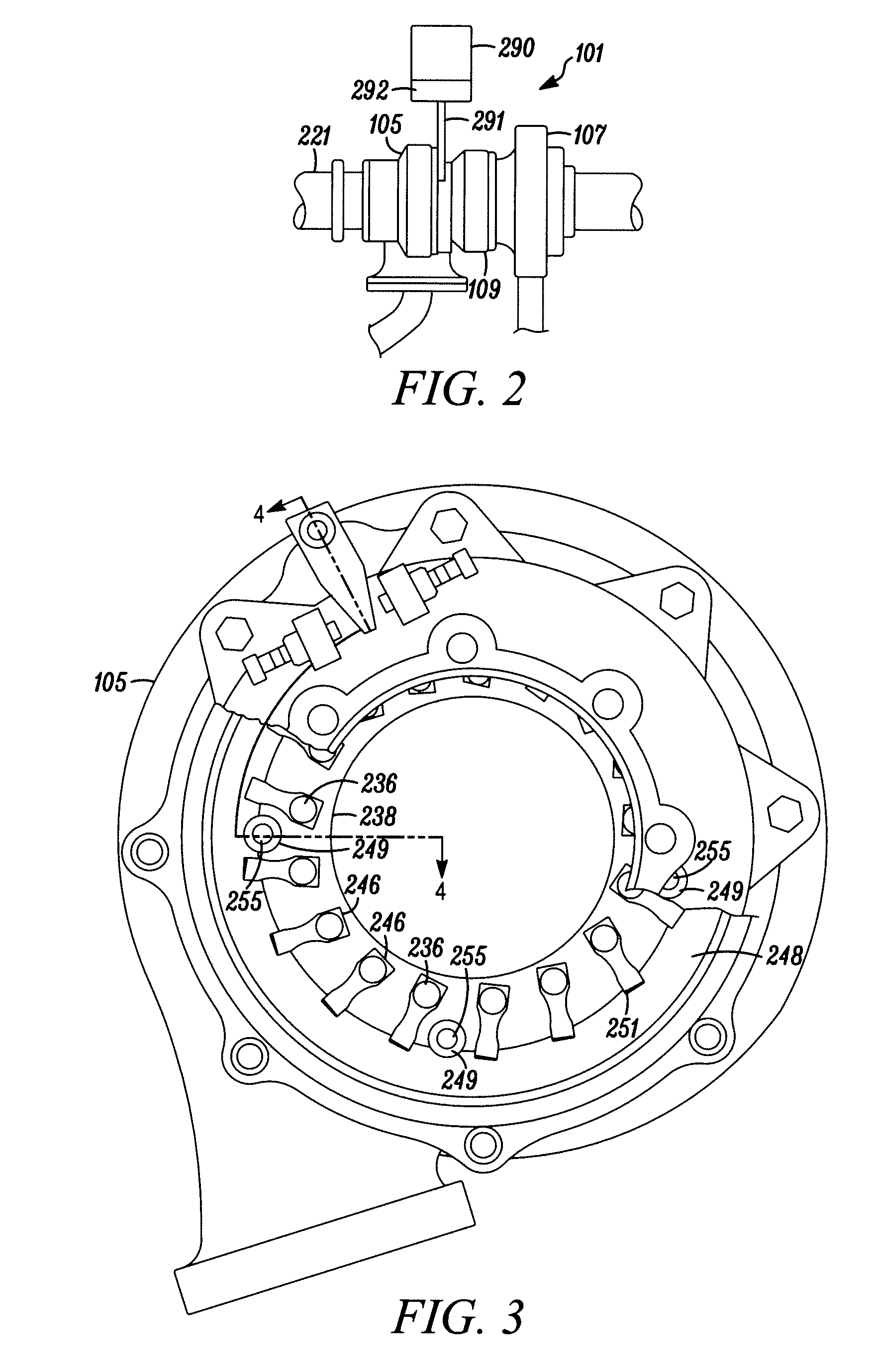
[0017]Typical embodiments of the present invention reside in a variable geometry controller for a turbocharger, along with associated methods and apparatus (e.g., compressors, turbochargers and turbocharged internal combustion engines). These embodiments are assemblies that provide for improved pressure ratios and / or related flow characteristics through the use of an actuation system implementing an adaptive control strategy configured to actuate a plurality of vanes exclusively through a range of positi...


PUM


Abstract

A variable geometry turbocharger employs multiple vanes in the turbine inlet with a unison ring and integral cast wall in the turbine housing forming the nozzle walls. An actuator rotates the unison ring through a rack and pinion driven crank shaft to move the vanes through a range of vane positions that extends between a hard-stop closed position and a hard-stop open position, and that includes a reference position corresponding to a desired flow condition. A variable geometry turbine controller uses a sensor indicating the actuation position of the actuator to guide the operation of the vanes to the reference position. The controller intermittently directs the actuator to force the vanes to the hard-stop closed and hard-stop open positions, and uses sensor information from those positions to reestablish the reference-position information that the actuator uses to guide the actuation of the vanes.

Description

[0001]This invention relates generally to the field of variable geometry turbochargers. More particularly, the present invention provides apparatus and methods for adjusting the calibration of actuated aerodynamic vanes in an inlet of a turbine housing as the actuation system wears with age and use.BACKGROUND OF THE INVENTION[0002]For a turbocharger, it is often desirable to control the flow of exhaust gas into the turbine to improve the efficiency or operational range. In a variable nozzle turbine (“VNT”), variable geometry members (e.g., vanes) are employed to control the exhaust gas flow. Typically, multiple pivoting vanes annularly positioned around the turbine inlet and commonly controlled to alter the throat area of the passages between the vanes is a commonly used design. Various approaches to this design are disclosed in U.S. Pat. Nos. 7,065,966, 4,679,984, and 4,804,316, which are incorporated herein by reference for all purposes.[0003]A typical VNT includes an actuator cap...

Claims


Application Information

Patent Timeline
Patent Type & Authority Applications(United States)
IPC IPC(8): F04D15/00F01D17/00
CPCF01D17/165F02B29/0406F02B37/013F02B37/24F02D23/00F02D41/0007F05D2270/62F02D41/2438F02D41/2464F02D2250/16Y02T10/144F05D2220/40F02D41/2432Y02T10/12
Inventor LOVE, ANDREW C.AGNEW, GARYSZCZYRBA, BAPTISTE
Owner GARRETT TRANSPORATION I INC
Why Eureka
Try Eureka