Massage machine

a massage machine and massage technology, applied in the field of massage machines, can solve the problems of insufficient massage feeling of the person to be treated and the inability to fix the distance between the left and right facing massage balls, and achieve the effect of great massage feeling

Inactive Publication Date: 2009-05-14
PANASONIC CORP
View PDF12 Cites 21 Cited by
  • Summary
  • Abstract
  • Description
  • Claims
  • Application Information

AI Technical Summary

Benefits of technology

[0007]According to the present invention, the distance from the drive shaft to the massage balls is large because of the presence of the swing arms, while the moving range of the massage balls is large because the upper and lower massage balls mounted on each support arm move in the same direction, so that a person to be treated can have great massage feeling.
[0008]The switching means switches the axial rotation position of the inclined shaft by switching the rotation direction of the drive shaft, the inclined shaft being able to idle in approximately 180° relative to the drive shaft. Thus, it is possible to switch between the state of kneading massage and the state of swing massage by switching the rotation direction of the drive shaft. Further, it is preferable that an elastic body is used to apply pressure to the inclined shaft in the axial direction of the drive shaft. This enables to avoid a situation that the inclined shaft is forced to rotate e.g. due to a load applied to the swing arm by a person to be treated, because the inclined shaft is able to idle at the time of the above-described switching.
[0009]The massage machine according to the present invention further comprises distance adjusting means for stopping the rotation of the drive shaft at an arbitrary position so as to make it possible to adjust the distance between the pair of left and right massage ball units, wherein the distance adjusting means rotates the drive shaft at least one rotation when adjusting the distance between the massage ball units. The distance adjusting means allows the drive shaft to be always placed at a predetermined position relative to the drive shaft, so that a person to be treated can securely adjust the distance between the massage ball units.
[0010]The massage machine according to the present invention further comprises drive means for providing a further movement to the pair of left and right massage ball units without depending on the rotation and driving of the drive shaft, wherein the drive means drives the massage ball units after rotating the drive shaft in one direction. The further movement described above refers e.g. to a movement of the massage ball units in a direction vertical to the surface of a backrest of the massage machine as in the tapping massage, while the drive means described above refers to an independent drive means which is separate from driving means for driving the drive shaft. When the drive means described above allows the massage ball units to perform the further movement (e.g. tapping massage), the drive shaft is first rotated in a predetermined rotation direction. This allows the inclined shaft to be set at a predetermined axial rotation position relative to the drive shaft, so that the further movement can be performed securely.
[0011]It is preferable that the drive shaft be rotated at a maximum speed when the distance adjusting means operates. This is in order to make it possible to more securely switch the relationship of the axial rotation position of the inclined shaft which is able to idle relative to the drive shaft.
[0012]The both ends of the drive shaft have a pair of eccentric shaft members having an axial center at a position eccentric from the center of the rotational axis of the drive shaft, wherein the swing arms of the pair of left and right massage ball units are respectively connected to the eccentric shaft members via the inclined shafts. This allows the eccentric shaft members to rotate with the rotational axis of the drive shaft as a center, so that the swing arms connected to the eccentric shaft members can add movement vertical to the front side of the backrest of the massage machine.

Problems solved by technology

Particularly, in the case of swing massage, sometimes a person to be treated cannot have sufficient massage feeling.
Further, the conventional massage machine allows one drive shaft to temporarily idle when switching between the state of swing massage and the state of kneading massage, so that sometimes the distance between the left and right facing massage balls is not fixed.

Method used


Image

  • Massage machine
  • Massage machine
  • Massage machine

Examples


Embodiment Construction

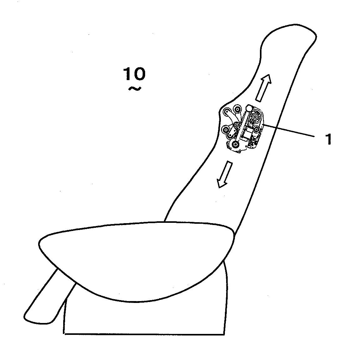
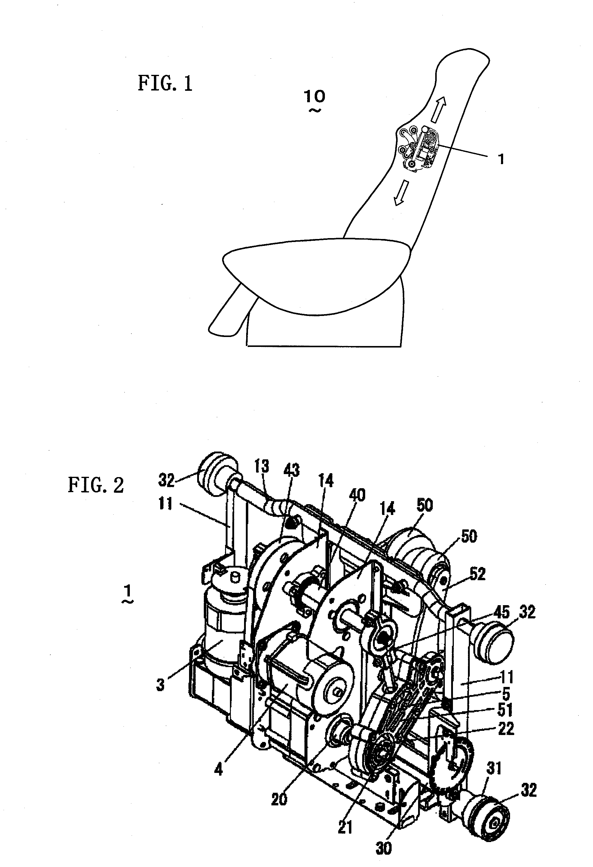
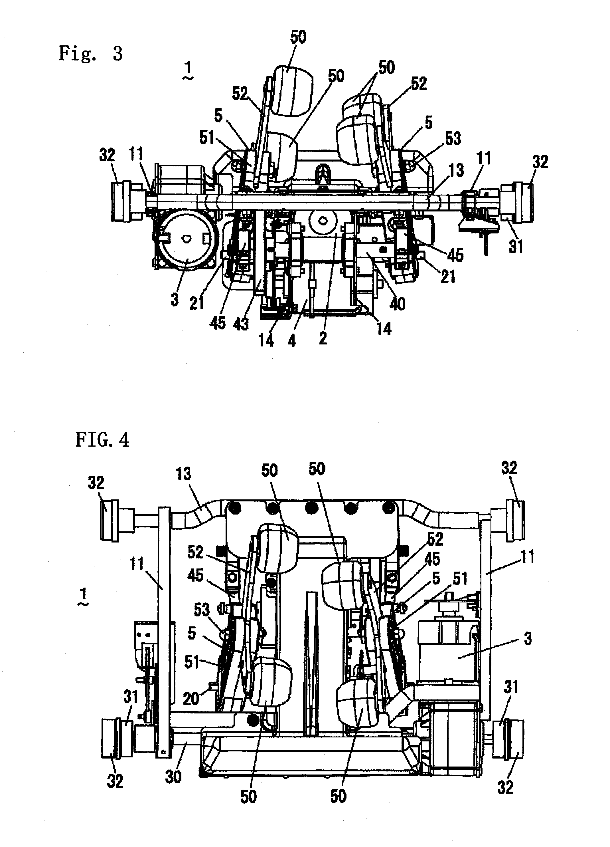
[0029]A massage machine according to an embodiment of the present invention will be described with reference to the drawings. As shown in FIG. 1, a massage machine 10 according to the present embodiment comprises a massage mechanism 1 arranged to autonomously move up and down in a backrest of a chair. As shown in FIGS. 1 to 6, the massage mechanism 1 is formed of a kneading drive motor unit 2 (refer to FIG. 3), an up-and-down drive motor unit 3, a tapping drive motor unit 4, a pair of left and right massage ball units 5, and so on, which are mounted in a frame formed of: a pair of left and right positioned vertical frame members 11; a guide shaft 13 connecting upper ends of the pair of vertical frame members 11; a moving shaft 30 disposed between lower ends of the vertical frame members 11; a pair of mounting plates 14 placed midway on the guide shaft 13; and so on. Note that FIG. 5 shows a slit plate 71 for moving position detection and a photosensor 72 for moving position detectio...


PUM


Abstract

A massage machine comprises a drive shaft rotatably driven in forward and reverse directions; a pair of inclined shafts mounted on both ends of the drive shaft so as to have an arbitrary inclination relative to an axial direction of the drive shaft; a pair of left and right massage ball units including massage balls and rotatably connected to outer peripheral surfaces of the pair of inclined shafts, respectively; and switching means for switching an axial rotation position of one inclined shaft of the pair of inclined shafts. The massage ball units each comprise a swing arm having one end rotatably connected to the outer peripheral surface of the inclined shaft; and a support arm connected to the other end of the swing arm and having mounted thereon multiple massage balls at a vertical distance from each other. Thus, according to the massage machine, the distance from the drive shaft to the massage balls is large because of the presence of the swing arms, while the moving range of the massage balls is large because the upper and lower massage balls mounted on each support arm move in the same direction, so that a person to be treated can have great massage feeling.

Description

TECHNICAL FIELD[0001]The present invention relates to a massage machine in which massage balls are swung to trace a three-dimensional trajectory so as to perform various treatments such as kneading massage, tapping massage and vibration massage.BACKGROUND ART[0002]In the prior art, a massage machine is known which uses the power of a driving unit to swing roller-shaped massage balls so as to massage the back of a person to be treated. As disclosed e.g. in Japanese Laid-open Patent Publication 2003-38591, a massage machine is known which comprises drive shafts rotated by a motor as a power source, and a pair of left and right swing arms arranged inclined to the drive shafts, in which multiple massage balls provided on these swing arms are moved left and right so as to give a kneading massage to the back of a person to be treated.[0003]In the massage machine disclosed in the Japanese Laid-open Patent Publication 2003-38591 described above, the drive shafts are separated between the re...

Claims


Application Information

Patent Timeline
Patent Type & Authority Applications(United States)
IPC IPC(8): A61H1/00A61H7/00
CPCA61H15/0078A61H2201/0149A61H2201/1669A61H2203/0431A61H2205/081A61H2201/1678A61H2015/0028A61H2201/1427A61H2201/1623A61H2201/1654A61H7/007A61H23/006A61H23/0254A61H15/00
Inventor NISHIO, FUMIHIROTANIZAWA, TAKAYOSHIMIYAGUCHI, MASAMICHINISHIBORI, YUICHITSUKADA, DAISUKEKAJIYAMA, SATOSHIKURATA, YOUSUKEDAIRIN, MASATOSHIIKEBE, MUNEKIYO
Owner PANASONIC CORP
Why Eureka
Try Eureka